🏛️ Advanced Kinematics & Background Grid Tracking Audit
- The Foundational Formula: Dr. Larry VanSuch’s Ultimate Running Speed Equation (URSE) Model.
- The Reference Mechanics: Evaluating historical 1987 treadmill locomotion tracking frameworks that utilized a fixed background wall grid to calculate distance and velocity data.
- The Mechanical Reality: Analyzing how a static wall-locked reference framework oversimplifies three-dimensional cross-axis joint torque into a flat, horizontal loop contradiction.
- The Structural Truth Revealed: Why the illusion of a stationary center of mass inside a treadmill cage masked the active, asymmetrical 3-vs-1 pelvic centrifuge engine.
Section 1: Analysis of the Background Calibration Hypothesis
In the field of modern sports biomechanics, historical 1987 treadmill locomotion literature stands as a heavily cited baseline regarding upper body tracking data collection.
For nearly forty years, standard athletic training templates and sport performance curricula have relied on early cinematic tracking models to evaluate the upper body’s role on the propulsive ledger.
Conventional literature established a baseline viewpoint that the upper extremities contribute zero active forward horsepower to overground running velocity.
When evaluating the primitive data-interpretation frameworks of early laboratory setups, however, a significant methodological limitation emerges within the initial reference geometry.
Early models arrived at a two-limbs-versus-two-limbs symmetrical wave cancellation conclusion because the software equations fumbled basic bipedal reference geometry.
To set up early cinematic tracking arrays, testing protocols positioned a stationary camera tripod on one side of a room, placed a motorized treadmill in the center, and mounted a large reference calibration grid wall directly behind the athlete.
This background grid wall was a rigid plane marked with precise horizontal and vertical measurement lines to help primitive computer software calculate distance variables.
Because early computer programs lacked the multi-axis processing power to map three-dimensional cross-axis joint torque, calculations anchored mathematical equations directly to that static reference board.
This methodology introduced a severe tracking error by measuring the motion of the moving limbs against a piece of static background furniture instead of calculating acceleration relative to the forward translating movement of the treadmill belt surface.
Section 2: The Symmetrical Cancellation Illusion
Conventional biomechanical tracking frequently builds its framework on top of a data-processing illusion born from a room-locked frame of reference.
Early testing configurations forced athletes to run on a motorized treadmill belt, yet the software equations evaluated movement relative to a static wall grid rather than the moving surface beneath the runner’s feet.
The raw data recorded by the laboratory hardware was highly precise, but the underlying interpretive framework lacked a multi-axis coordinate blueprint to map the vectors accurately.
Legacy models arrived at a symmetrical cancellation conclusion based entirely on the illusion of a stationary center of mass inside a treadmill testing cage.
Because the motorized belt kept the runner’s torso from advancing lineally through space, the early software projected a perfectly mirrored visual loop of the swinging arms directly against the moving legs across the vertical square lines of the background wall board.
Because the arm arcs and leg lines appeared to evenly match and mirror each other against that static piece of background plywood, standard publications delivered the definitive conclusion that the upper mass merely offsets the lower mass.
We can openly evaluate this foundational historical curriculum with a direct engineering cross-examination:
if the human upper body is a passive spectator designed to execute a symmetrical two-versus-two loop cancellation against a static piece of wall furniture, how does a bipedal engine balance a violent cross-axis torque avalanche across a wide pelvic axle?
Section 3: Deleting the Background Grid Code: The URSE Pelvic Ledger
To deliver the true biological source code to track coaches and robotics developers, we must bypass these primitive reference shortcuts and apply the unyielding engineering constants of the Ultimate Running Speed Equation (URSE) pelvic roadmap:
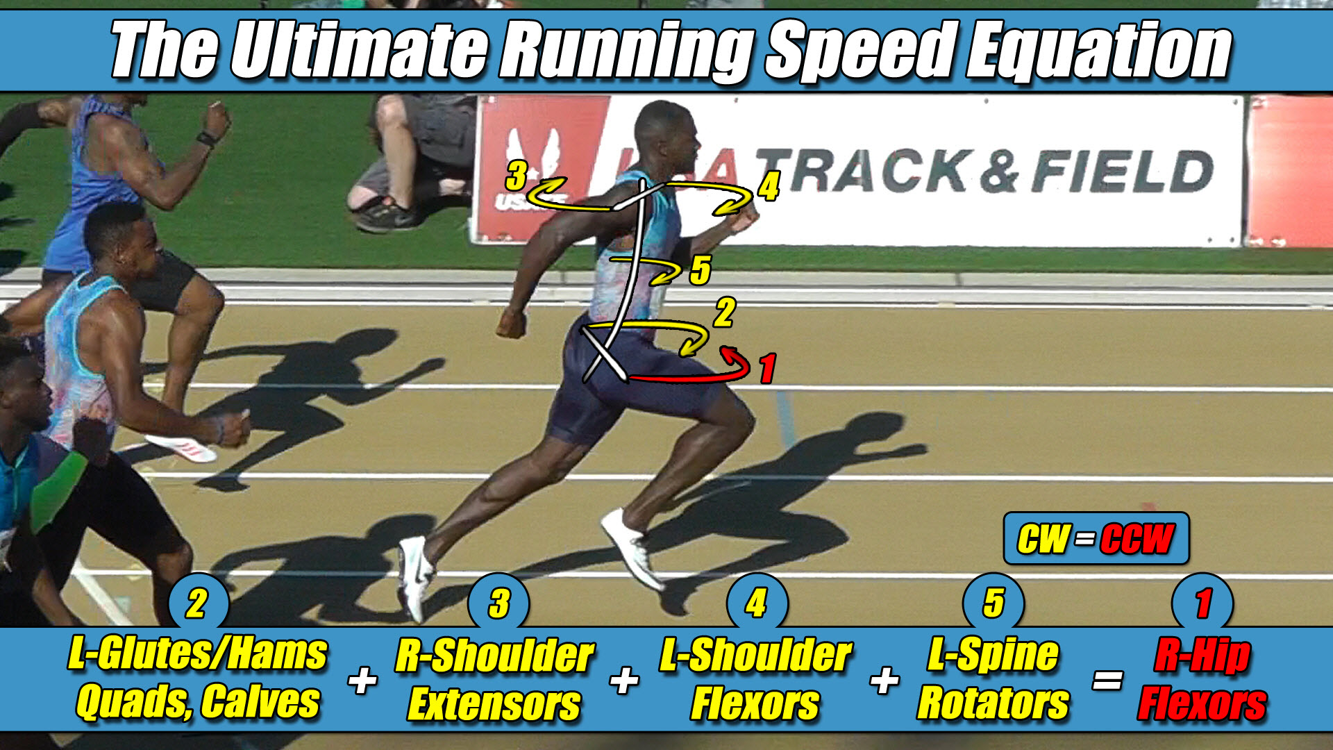
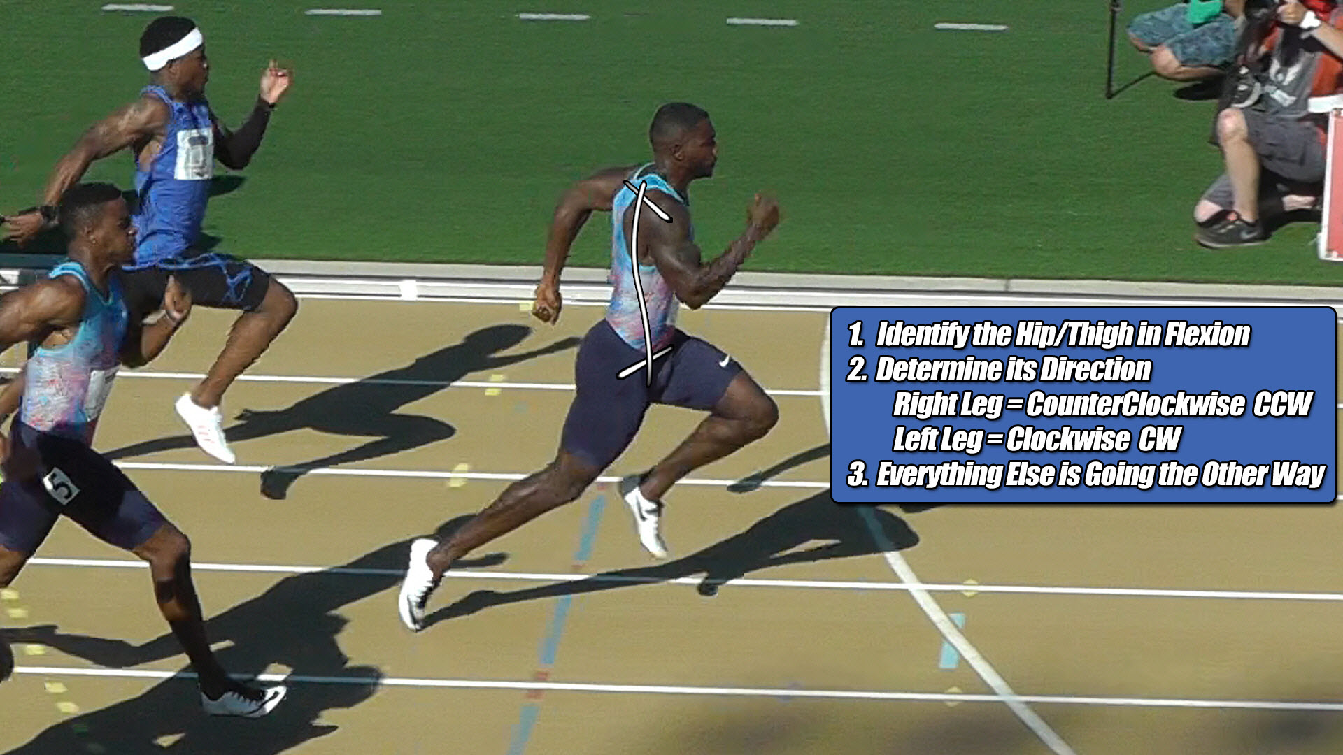
- ⚡ Law 1: The Permanent Leg Side Constants — The side of the leg is a strict, unyielding constant; the Right Leg always projects Counter-Clockwise (CCW) torque across the pelvic axle, and the Left Leg always projects Clockwise (CW) torque—regardless of whether they are in flexion or extension.
- ⚡ Law 2: The United Upper Body Multiplier — The upper body rotators and arms function as one single unit with respect to rotation.
- ⚡ Law 3: The Alternating Alliance — Acting as a single unit, the upper body rotators and arms function as high-speed torque multipliers, actively alternating their collective torque patterns to match, favor, and reinforce whichever pushing leg is currently anchored to the turf.
- ⚡ Law 4: The Solitary Counterweight Balance — The unweighted, airborne swing leg must contract at extreme fast-twitch velocities to rise up and completely match the combined torque load of the active pushing team (pushing leg, both arms, torso) to bring Net Torque to exactly Zero.
The URSE framework proves that human running is never a neat, comfortable two-versus-two game of top-versus-bottom cancellation.
In the real physical universe, human hip sockets sit permanently, laterally displaced away from the central midline of the spine.
Because of this wide pelvic offset, the exact millisecond a runner’s right foot, for example, strikes the track and projects force backward, that drive line naturally unleashes a violent Counter-Clockwise (CCW) torque avalanche across the pelvic axle under URSE Law #1.
Traditional models fumbled the basic rules of Newtonian mechanics by assuming that because their sensors registered a net angular momentum near zero in the twisting transverse plane, the upper body was a passive dead zone.
This viewpoint remains blind to the reality that a net zero calculation is the highly active, high-horsepower result of a massive, ongoing torque battle across the spine.
The arms are not passive mass-dampers trapped inside a symmetrical loop.
Under URSE Law #3, they are active multipliers that align with the grounded stance column and torso to form a dynamic, three-limbs-versus-one-limb centrifuge engine.
The only reason real-world treadmill subjects do not spin out of control or suffer joint injury under intense load is because this asymmetric three-limbs-versus-one-limb engine runs at absolute mechanical perfection to pull the net pelvic ledger back to zero under URSE Law #4.
Section 4: Single-Axis Vector Models versus Multi-Axis Coordinate Frameworks
The global proliferation of modern speed fallacies relies on conventional frameworks that accepted early background tracking errors without calculating cross-axis rotational variables.
Subsequent velocity studies utilized this primitive upper-body blackout to declare that overground speed is dictated solely by how hard a single leg column can stomp straight down into a vertical force plate.
Downstream adaptations took this single-piston philosophy and turned it into simplified software models that treat ninety-two percent of the human body as a rigid, non-rotating block sliding along a vertical track.
These models evaluate a low-level game of vertical tracking angles based on an illusion inherited from early treadmill reference frames, remaining completely blind to the reality that human locomotion is a three-dimensional coordinate engine.
By passing these shared baseline data curves through original pelvic constants, the true mechanical purpose of full-body coordination is revealed.
The central nervous system does not operate based on flat kinematic drawing angles or rigid pogo-stick simulations.
The body can program whatever overground foot strike or arm angle variation it requires; your internal cross-axis centrifuge will instantaneously calculate and adapt the remaining limbs to keep Net Torque at Zero.
A three-dimensional coordinate perspective allows coaches and practitioners to work directly with physics to maximize structural movement efficiency.
Until athletic performance software, advanced military robotics labs, and track certification panels update their tracking code bases and move past single-axis models, their training templates and bipedal machines will remain completely trapped inside an artificial strategy void.


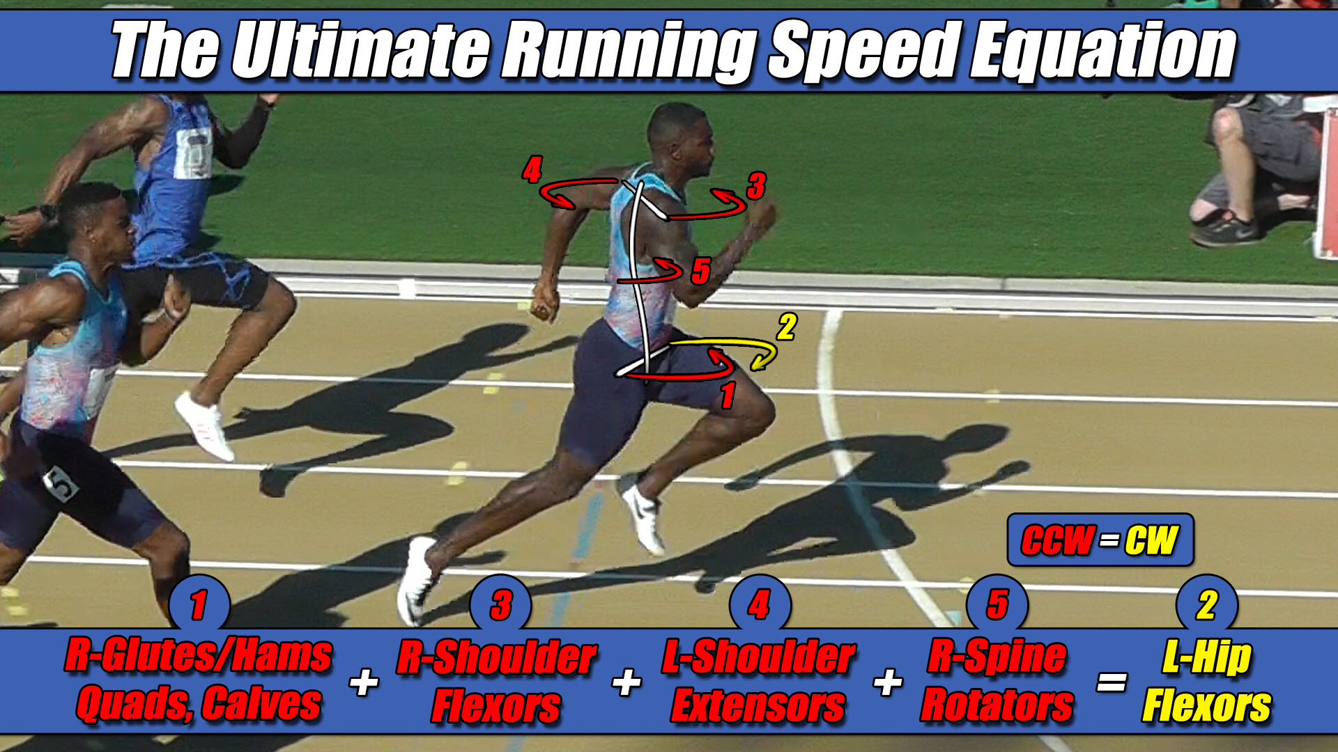 Left Hip Flexor Torque = CW. Everything Else CCW.