🏛️ Advanced Kinematics & Angular Momentum Waveform Audit
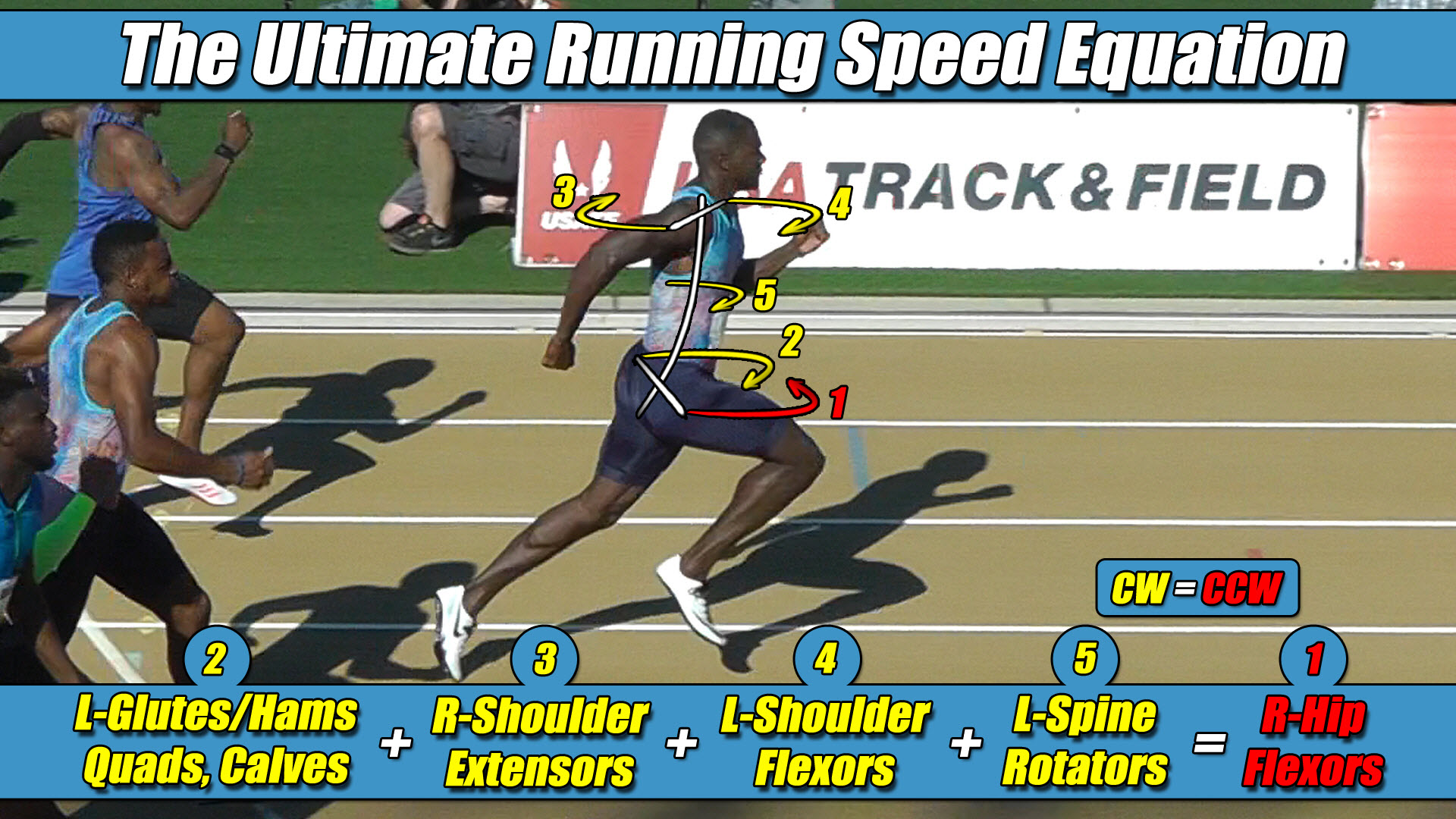
- The Foundational Formula: Dr. Larry VanSuch’s Ultimate Running Speed Equation (URSE) Model.
- The Reference Mechanics: Evaluating legacy 1987 laboratory data charts examining total body angular momentum waveforms during motorized treadmill testing configurations.
- The Mechanical Reality: Analyzing how a flat, relative-to-torso equation oversimplifies three-dimensional cross-axis joint torque by grouping the limbs into binary upper and lower body blocks.
- The Structural Truth Revealed: Why a recorded twenty percent wave deficit on relative angular momentum graphs serves as direct physical validation of the 3-vs-1 multi-axis centrifuge engine.
Section 1: The Symmetrical Mirrored-Loop Hypothesis
In the field of modern sports biomechanics, historical 1987 treadmill locomotion literature stands as a heavily cited baseline regarding upper body tracking data collection.
For nearly forty years, standard athletic training templates and sport performance curricula have relied on early kinetic models to evaluate the upper body’s role on the propulsive ledger.
Conventional literature established a baseline viewpoint that the upper extremities contribute zero active forward horsepower to overground running velocity.
When evaluating the data-interpretation frameworks of early laboratory setups, however, a significant reference frame limitation emerges within the initial calculation panels.
Early models arrived at a two-limbs-versus-two-limbs symmetrical wave cancellation conclusion because the software equations fumbled basic bipedal reference geometry.
Traditional sports-science boards teach the artificial doctrine that the entire upper body mass simply twists in one direction while the entire lower body mass twists harmoniously in the other to wash out rotational force altogether.
To make this balanced formula work on paper, legacy textbooks rely on a highly specific, manufactured two-versus-two numerical grouping.
They mathematically combine the two upper extremities into a single upper-body block, and pit them against the two lower extremities acting as a single lower-body block.
They assume that because these limbs are paired up in an even two-against-two format, their respective twisting patterns automatically balance the skeleton to a perfect draw.
An unyielding three-dimensional engineering analysis reveals that real human locomotion actually operates on an asymmetric three-limbs-versus-one-limb framework, where both arms and the grounded pushing leg operate in rotational unison.
Section 2: How the Mainframe Manufactured the Two-Versus-Two Illusion
To figure out why total body rotation summed close to zero on early instruments, conventional software was programmed to split a multi-segment stick-figure model into separate mathematical piles on spreadsheet calculators.
The extremities were grouped into an upper group pile containing both arms combined with the head and torso, and a lower group pile containing both legs combined.
When evaluating the resulting angular graph outputs, early computer screens printed out two perfectly mirrored waves.
At the exact millisecond the lower leg group projected a wave of Clockwise (CW) rotation on the chart, the upper arm group projected a matching wave of Counter-Clockwise (CCW) rotation.
This orientation automatically reversed during the very next step of the stride cycle.
Because the wave of the upper group mirrored and canceled out the wave of the lower group on the screen, early theory arrived at its two-versus-two conclusion.
It was assumed that the two legs work together as one team to twist the lower half of the body, while the two arms work together as a separate team to twist the upper half of the body in reverse.
However, a closer examination reveals that the entire two-versus-two rotational claim is an artificial representation born because the data model combined the two legs before looking at the underlying physics.
By lumping the right leg and left leg together into a single lower body block, the software took an asymmetric torque balance between the two limbs and smeared it out into a smooth average.
Section 3: The Wave Deficit on the Original Charts
Inside published relative angular momentum charts, the combined upper arm group and lower leg group wave lines never actually achieved a perfect one hundred percent cancellation loop on paper.
Historical documentation explicitly notes that the upper and lower body masses didn’t completely cancel to a flat zero line, but merely came close.
The remaining net total line on the monitor screen consistently leaked a noticeable leftover wave that favored and swung in the direction of the leg group’s rotation.
This mathematical remnant represents a critical technical discrepancy, because a real-world athlete over solid ground runs in absolute physical perfection where Net Total Body Torque is always a flawless Zero.
If a human being’s internal skeletal torque engine actually mismatched by a massive margin at elite velocities, the structural framework would be forced offline by uneven rotational forces.
The reason these legacy charts printed out an unbalanced remnant inside the computer is because the spreadsheet script was forcing an artificial two-versus-two model to calculate a three-dimensional, three-limbs-versus-one-limb pelvic engine.
Because early software assistants only tracked coordinate markers moving against a flat background board while the treadmill belt kept the runner’s torso frozen in space, the code fumbled the true rotational inputs of overground locomotion.
When looking down from a bird’s-eye view, both arms actively swing in a way that forces the upper torso to twist in the exact same circular rotational direction, doubling their combined angular momentum wave on the charts.
To calculate the lower body block, the legacy spreadsheet script simply combined the forward coordinate arc of the swing leg with the backward moving arc of the stance leg.
Section 4: The Core Engineering Laws of the URSE Model
The universal balance constants of biomechanics dictate that the true engineering reality of human flight is a multi-axis balance of torques across separate axles, governed by the constants of the Ultimate Running Speed Equation (URSE) model:
- ⚡ Law 1: The Permanent Leg Side Constants — The side of the leg is a strict, unyielding constant; the Right Leg always projects Counter-Clockwise (CCW) torque across the pelvic axle, and the Left Leg always projects Clockwise (CW) torque—regardless of whether they are in flexion or extension.
- ⚡ Law 2: The United Upper Body Multiplier — The upper body rotators and arms function as one single unit with respect to rotation.
- ⚡ Law 3: The Alternating Alliance — Acting as a single unit, the upper body rotators and arms function as high-speed torque multipliers, actively alternating their collective torque patterns to match, favor, and reinforce whichever pushing leg is currently anchored to the turf.
- ⚡ Law 4: The Solitary Counterweight Balance — The unweighted, airborne swing leg must contract at extreme fast-twitch velocities to rise up and completely match the combined torque load of the active pushing team (pushing leg, both arms, torso) to bring Net Torque to exactly Zero.
The true multi-axis balance law involves three limbs working on a unified team against one solitary limb:
(Airborne Swing Leg) Torque = (Left Arm + Right Arm + Pushing Leg + Torso) Torque
with respect to limbs: 3-vs-1
Section 5: The Data Deficit and the Missing Ledger Column
The ultimate proof that a two-versus-two model fumbled the laws of mechanics was sitting directly on early computer monitors.
Because treadmill setups and flat relative-to-torso equations completely zeroed out forward linear translation vectors, the true forward propulsive torque contribution of the ground-bound pushing leg completely evaporated from the calculation loop.
Because the pushing leg’s true torque was mathematically removed from its side of the ledger by the room configuration, the high-velocity airborne swing leg stood completely unchecked on its side of the computer script.
Inside the spreadsheet software, the unweighted swing leg completely dominated and overwhelmed the arms.
Because two freely swinging arms alone do not possess the total mass-moment of inertia to equal an entire unweighted lower limb firing forward at terminal velocity, the arms had no mathematical leverage to cancel out that rolling leg wave without the pushing leg’s torque working directly alongside them.
Instead of questioning an artificial two-versus-two limb grouping or auditing frozen center of mass reference frames, legacy frameworks accepted this tracking deficit as standard laboratory variance.
They looked at a graph line where the upper group wave merely came close to the lower group wave, not realizing that both arms were actually teaming up with the pushing leg to fight the dominant torque of the solitary swing leg.
Early data compilation took an asymmetric three-limbs-versus-one-limb centrifuge engine, forced it into a flat two-versus-two group-averaging box, and mistook a lopsided skeletal torque battle for a harmonious, cooperative balance routine.
The tragedy of this multi-generational academic saga is that the data required to fix these equations was never recorded by early setups.
Because early teams relied entirely on visual coordinate kinematics and lacked active force-plate hardware beneath the treadmill deck, they omitted the pushing leg’s active propulsion column from the ledger, treating full-body rotation as a passive dead zone.
Section 6: Single-Axis Vector Models versus Multi-Axis Coordinate Frameworks
The reliance on these historical planar models influenced modern textbooks, coaching complexes, and athletic design frameworks globally.
Downstream researchers stepped into this data deficit and used these incomplete, room-insulated definitions to construct increasingly simplified models.
Early overground velocity papers utilized this flat baseline to establish a vertical-force monopoly, instructing coaches to view the lower limb as an isolated linear piston.
Later frameworks codified this vertical paradigm by inventing simplified spring-mass equations, whittling ninety-two percent of the active human machine down to a rigid, non-rotating block sliding along a vertical track.
Modern adaptations carried this linear trajectory to the international clinic circuit, promoting high-load, heavy sled-towing templates that completely lock down true pelvic torque expression and create instant speed plateaus.
By passing these celebrated vertical charts through original pelvic constants, the true mechanical purpose of ground force generation is revealed.
There are no passive springs, and there are no hidden linear shortcuts.
The ground reaction forces scale at high velocities because the full-body URSE engine is running at absolute mechanical perfection to keep Net Torque at Zero.
Utilizing a multi-axis coordinate framework resolves these historical translation challenges, transforming abstract datasets into a clear, functional blueprint that restores the true physics engine of human locomotion to the performance community.


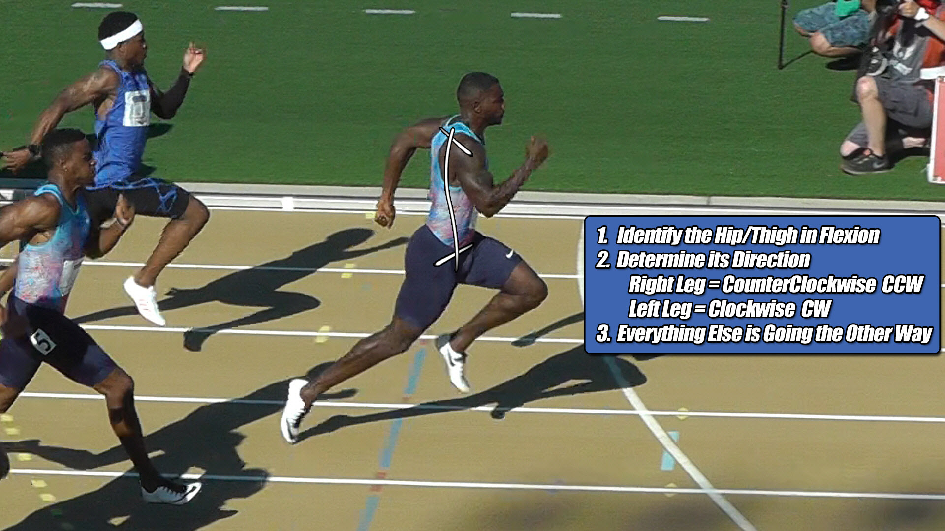
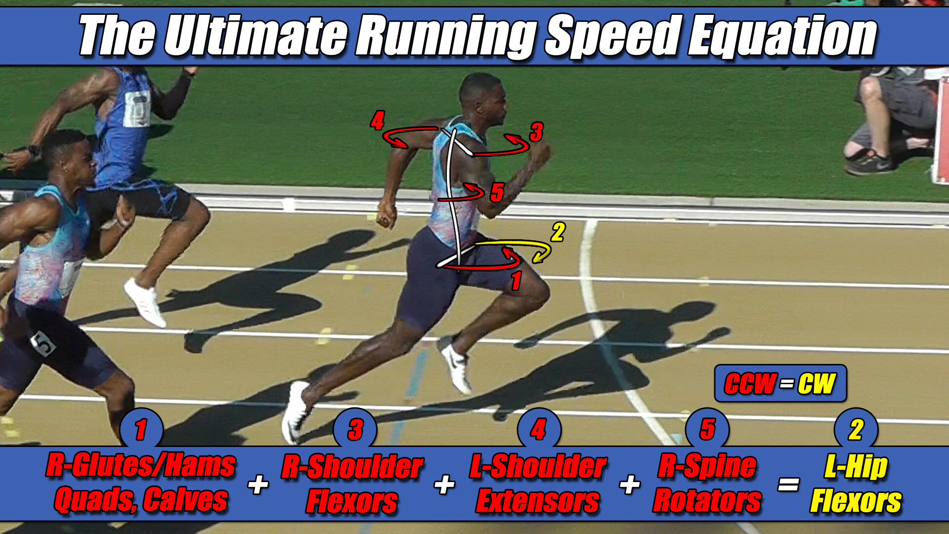 Left Hip Flexor Torque = CW. Everything Else CCW.