
Home » Science & Technology » Locomotion Research Reviews » Coordinate Sign Conventions and Angular Momentum in Locomotion: A Biomechanical Review of Room-Locked Reference Frame Data
🏛️ Advanced Kinematics & Reference Frame Velocity Audit
- The Foundational Formula: Dr. Larry VanSuch’s Ultimate Running Speed Equation (URSE) Model.
- The Reference Mechanics:
Evaluating historical 1987 treadmill angular momentum datasets that mathematically combined individual limbs into binary upper and lower extremity blocks.
- The Mechanical Reality: Analyzing how a static, room-locked camera reference frame reduces the relative overground linear velocity of backward-moving assets to near zero on spreadsheets.
- The Structural Truth Revealed: Why traditional two-versus-two symmetrical wave models collapse under relative acceleration variables into an asymmetrical 3-vs-1 multi-axis torque centrifuge.
Section 1: Analysis of the Hardcoded Sign Convention Paradox
In the field of modern sports biomechanics, historical 1987 angular momentum literature stands as a heavily cited baseline regarding three-dimensional treadmill data tracking.
When evaluating the foundational setup of historical tracking protocols, a significant methodological limitation exists within the initial data configuration panels.
If a data model groups individual moving limbs into single mathematical blocks and applies fixed tracking constraints, the configuration pre-determines the directional relationship of the output waveforms before calculations ever start.
To evaluate these classic spreadsheets objectively, the analysis must examine the directional logic and coordinate mapping systems rather than the raw numerical torque values recorded on laboratory monitors.
When setting up early three-dimensional tracking software, computer algorithms require a fixed reference framework to turn visual recording segments into mathematical vectors.
Traditional tracking configurations program coordinate systems based on standard rigid-body segment definitions.
They designate forward movement through the side-view sagittal plane as the primary tracking lane.
To track rotation in the twisting transverse plane, software scripts are explicitly configured with a strict directional sign convention: Counter-Clockwise (CCW) movement is mathematically labeled as Positive, and Clockwise (CW) movement is mathematically labeled as Negative.
Section 2: Approximation Errors and Flat Spatial Paths
Because early laboratory camera setups were focused on a static wall grid, they primarily registered flat, horizontal translation paths rather than true three-dimensional joint torque mechanics across a wide pelvic axle.
The software watched the right arm advance forward across room grid lines while the right leg pushed backward across a motorized treadmill belt.
Because these limbs moved in opposite horizontal directions past the camera lens, conventional analysis assumed they must be generating opposite, self-canceling angular torques.
This horizontal assumption introduces a severe directional layout error under strict cross-axis vector analysis.
To accurately map this configuration, we apply the unyielding mechanical realities of the Ultimate Running Speed Equation (URSE) core model:
- The Baseline Error — Legacy models observed a forward arm moving forward horizontally and a stance leg pushing backward horizontally, assuming that opposite horizontal translation paths equal opposite angular rotation vectors.
- The Overground Correction — According to URSE Law #1, the Right Leg driving backward during the grounded pushing phase always generates a permanent Counter-Clockwise (CCW) torque vector across the pelvic axle to power the chassis forward.
- The Perfect Alliance — Because the Right Arm driving forward also generates a powerful Counter-Clockwise (CCW) torque vector across the shoulder girdle as part of URSE Law #3, the upper and lower extremities work in compounding angular harmony to twist the pelvis.
By layout-mapping this cross-axis team alignment, it becomes clear that uniform coordinate signs oversimplify the data and invert the true rotational reality of the human drivetrain.
Traditional models constructed a flat coordinate setup that mistook alternating horizontal translation for a rotational alignment based on a series of structural contradictions:
- The Pushing-Side Team Harmony — On the active drive axle, the pushing leg moving backward and the forward arm pumping forward both generate a compounding Counter-Clockwise (CCW) torque vector, locking them into perfect angular harmony to twist the pelvis.
- The Swing-Side Asymmetrical Mismatch — This structural alignment does not apply on the opposite side of the skeleton, as the unweighted swing leg violently fires Clockwise (CW) through empty air while the posterior arm drives Counter-Clockwise (CCW).
- The Pelvic Drivetrain Reality — By remaining unaware of these asymmetric cross-axis properties, conventional sign conventions attempt to force a uniform, symmetrical calculation onto an inherently asymmetric biological machine.
The opposing waveforms printed on legacy monitors simply because the room-locked reference frame had completely zeroed out the relative velocity inputs of the backward-moving assets.
The software ran a fragmented calculation loop that only registered the un-canceled forward acceleration tracks of the forward arm (CCW) and the opposite swing leg (CW).
It remained blind to the reality that the pushing leg (CCW), the forward arm (CCW), and the trailing arm (CCW) were actually working in compounding angular harmony to twist the pelvis, establishing a 3-vs-1 relationship instead of a symmetrical two-versus-two model.
Section 3: The Double-Bind Summation Trap
A double-bind is a structural engineering flaw that constructs an inescapable trap where every single operational choice available guarantees calculation failure.
By choosing to group individual limbs together into a single upper extremity block and lower extremity block, legacy mainframes were forced to perform a flat, binary calculation loop.
By attempting to mathematically combine both legs together to generate a single line on a graph, the data sheets collided straight into an unyielding architectural dead end.
On paper, traditional bipedal modeling assumes that the lower extremities simply alternate directions in agreement with one another depending entirely on the cyclical swing-and-stance phase of the stride cycle.
But even this baseline assumption is fundamentally broken inside a room-insulated treadmill setup, because the active ground-bound propulsion vector is mathematically eliminated by the reference frame math before calculations ever begin.
Downstream linear models still stand entirely on historical datasets that eliminated the pushing leg’s true horizontal contribution from entering their findings.
They subsequently push for high-load vertical force templates and heavy, linear training methods that assume full-body rotation is a completely passive dead zone.
Conventional speed philosophies built an entire multi-generational paradigm on top of studies that inadvertently blacked out the exact driving axle they claim to be analyzing.
The calculations hit a limitation no matter what move was executed; data collection fumbled by deleting the pushing leg’s input from the ledger, and had the system actually included it, the hardcoded coordinate signs would have miscalculated its true torque direction anyway:
- The Deletion Error — Traditional data collection fumbled the headcount by using a room-locked treadmill frame that completely zeroed out the relative velocity input of the pushing leg, reducing its column to a non-factor.
- The Rotational Direction Error — Had the system bypassed that frame error and captured the pushing leg, the pre-engineered coordinate sign script would have miscalculated its true torque direction by forcing its backward horizontal path into an artificial Clockwise box.
Because the backward pushing leg’s linear velocity matched the speed of the treadmill belt, its acceleration value relative to the fixed room grid was reduced to near zero.
This meant the active drive axle was completely eliminated as a functional factor inside the software, leaving its column header on the spreadsheet empty.
Instead of mashing two active, balancing limbs together, the data-averaging shortcut took the massive forward sweep of the single airborne swing leg and poured it over an empty data slot.
The unchecked momentum of that flying swing leg completely swallowed the zeroed-out pushing leg’s column, masking real-world pelvic constants behind an absolute mathematical fiction.
Section 4: The Dual-Axle Eradication Strategy
Let’s evaluate the sheer weight of what these programming shortcuts did to actual spreadsheet headers:
- The Lower Axle Eradication — The treadmill reference frame zeroed out the pushing leg, turning a high-horsepower drive axle into an empty spreadsheet slot.
- The Upper Axle Eradication — The exact same room-locked equation zeroed out the backward-swinging arm, erasing its massive structural contribution from the top column group.
These shortcuts benched half the starting lineup on the field.
The programming shortcuts erased not only the active driving axle of human locomotion before calculations ever started but also another contributing member in the backward-swinging arm.
The headcount was compromised on both sides of the pelvis, transforming a magnificent biological engine into two lonely swinging sticks and passing off a fragmented, isolated matchup as an absolute law of athletic performance.
Section 5: The Isolated Headcount and the Velocity Illusion
The discrepancy inside legacy laboratory scripts runs deeper than a simple directional trick.
The data sheets were not running a genuine two-versus-two calculation between four independent, functioning limbs.
Because the camera tripod was bolted to a static room coordinate and focused on a background grid board, the software calculated forward linear velocity strictly relative to that static wall.
The exact millisecond a leg hit the treadmill deck to drive propulsion backward, its relative linear velocity dropped to near zero on the spreadsheet because its movement perfectly matched the backward speed of the treadmill belt.
The exact same physical erasure happened to the trailing arm, whose backward acceleration relative to the chest was completely zeroed out by room-locked equations.
This left the mathematical system performing a direct, isolated matchup between just two remaining forward-moving limbs: the forward arm (Positive CCW) and the opposite swing leg (Negative CW).
The only reason the final charts printed out a beautifully balanced total line that created the optical illusion of all four limbs neatly accounting for each other is because the soaring, double-velocity forward components mathematically made up for the absent, zeroed-out backward ones.
The massive, towering forward waves of the single forward arm and single swing leg completely swallowed the flat, zeroed-out data slots of the missing drive assets inside the group columns.
Section 6: The Extended Scale Computational Mismatch
Traditional data models did not balance cleanly to a net zero overground; they simply reduced the number of active players on spreadsheets to make the data leak look manageable.
Instead of calculating all four moving limbs across their full operational envelopes, room-insulated equations effectively benched the primary drive assets and only calculated a single sector of horizontal movement.
By restricting the field of view to a fragmented, isolated silhouette, the final score on laboratory monitors printed out a minor leftover wave mismatch.
But because a real human leg column is significantly longer and heavier than an arm extremity, squaring that massive lower-limb radius (r²) acts as an absolute exponential amplifier in the real physical universe.
The moment room boundaries are thrown out of the equation and calculations evaluate a full overground stride, the actual differences in the radius and mass of the extremities completely destroy a simple pendulum paradigm.
Pitting a single thinned-down arm column against the massive, squared-length engine of the opposing swing leg results in an absolute computational mismatch.
When calculated under the real-world laws of relative acceleration, the true kinetic variables completely overpower the arm’s standalone capacity.
Legacy frameworks evaluated a lopsided chart remnant, flattened the vertical angular momentum wave deficit against a three-dimensional total-body template to hide the leak, labeled a massive twisting plane mismatch relatively small, and allowed forty years of speed training manuals to promote a restricted calculation error as an absolute law of human flight.
Section 7: The Core Engineering Laws of the URSE Model
Human locomotion is an unyielding battle of balancing rotational torque constants across your pelvis, where Net Torque must equal exactly Zero.
The following four laws are universal biomechanical constants that hold the absolute mathematical key to answering every question regarding arm function, athletic speed limitations, training plateaus, and genuine running efficiency:
- ⚡ Law 1: The Permanent Leg Side Constants — The side of the leg is a strict, unyielding constant; the Right Leg always projects Counter-Clockwise (CCW) torque across the pelvic axle, and the Left Leg always projects Clockwise (CW) torque—regardless of whether they are in flexion or extension.
- ⚡ Law 2: The United Upper Body Multiplier — The upper body rotators and arms function as one single unit with respect to rotation.
- ⚡ Law 3: The Alternating Alliance — Acting as a single unit, the upper body rotators and arms function as high-speed torque multipliers, actively alternating their collective torque patterns to match, favor, and reinforce whichever pushing leg is currently anchored to the turf.
- ⚡ Law 4: The Solitary Counterweight Balance — The unweighted, airborne swing leg must contract at extreme fast-twitch velocities to rise up and completely match the combined torque load of the active pushing team (pushing leg, both arms, torso) to bring Net Torque to exactly Zero.
The upper extremities and torso actively align with the grounded stance column to form a dynamic, three-limbs-versus-one-limb centrifuge engine.
Instead of fighting the skeleton to absorb loose energy vibrations, the active pushing team acts as a unified high-horsepower torque multiplier, while the solitary airborne swing leg completes the mechanical loop to forge a perfect dynamic balance of zero net vertical torque.
Section 8: Tracing the Multi-Generational Structural Lineage
For nearly forty years, the structural limitations embedded within early data-processing shortcuts have inadvertently influenced the sports performance complex.
By lumping individual moving limbs into flat, binary block configurations to simplify primitive computer script calculations, foundational data models accidentally obscured the true three-dimensional mechanics of overground movement.
This historical blind spot created an unintended academic vacuum that fundamentally misdirected conventional understandings of running and sprinting efficiency.
Because this original framework mathematically erased the ground-bound pushing leg’s active propulsion column and treated full-body rotation as a passive dead zone, it left future investigators without a complete mechanical ledger.
Downstream researchers stepped into this data deficit and used these incomplete, room-insulated definitions to construct increasingly simplified models:
- The Vertical Force Monopoly — Early overground velocity papers utilized this flat baseline to establish a vertical-force model, instructing coaches to view the lower limb as an isolated linear piston.
- The Two-Mass Model — Later frameworks codified this vertical paradigm by inventing simplified spring-mass equations, whittling ninety-two percent of the active human machine down to a rigid, non-rotating block sliding along a vertical track.
- The Heavy Sled Paradigm — Modern adaptations carried this linear trajectory to the international clinic circuit, promoting high-load, heavy sled-towing templates that completely lock down true pelvic torque expression.
By tracing this multi-generational lineage back to its original historical source, the modern speed training illusion completely self-destructs.
The human sprint engine is not a passive, one-dimensional pogo stick bouncing on a vertical rod.
It is an active, high-horsepower rotational machine driven by leverage and torque—governed entirely by your 3-vs-1 multi-axis centrifuge constants.
📜 Applying Dr. VanSuch’s Rosetta Stone: 3-Step Process For Decoding Torque Patterns in Bipedal Locomotion
Decoding Torque Pattern 1 of 2
Apply the three steps to the runner in the figure below to determine the first of two torque patterns everyone shares for not just sprinting, but all human locomotion… walking, jogging, running:
- Identify the hip/thigh in flexion. This is what you need to key in at the very beginning. In the image below, it’s the left hip.
- Determine the torque direction of this hip/thigh based on the following constants: Right Leg = CCW Left Leg = CW. Therefore, Since we identified it was the left hip, we know it’s CW.
- Everything else is going the other way. In this case, that means the pushing leg, left arm, right arm, torso = CCW.
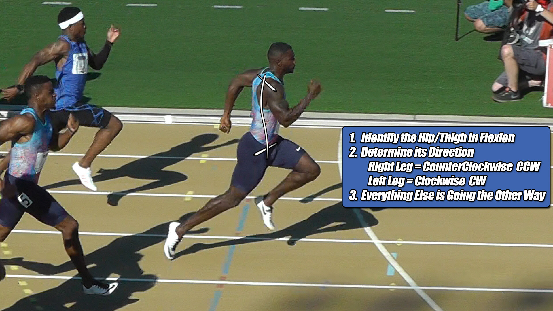
The first of two torque patterns everyone shares for not just sprinting, but all human locomotion… walking jogging, running is shown below:
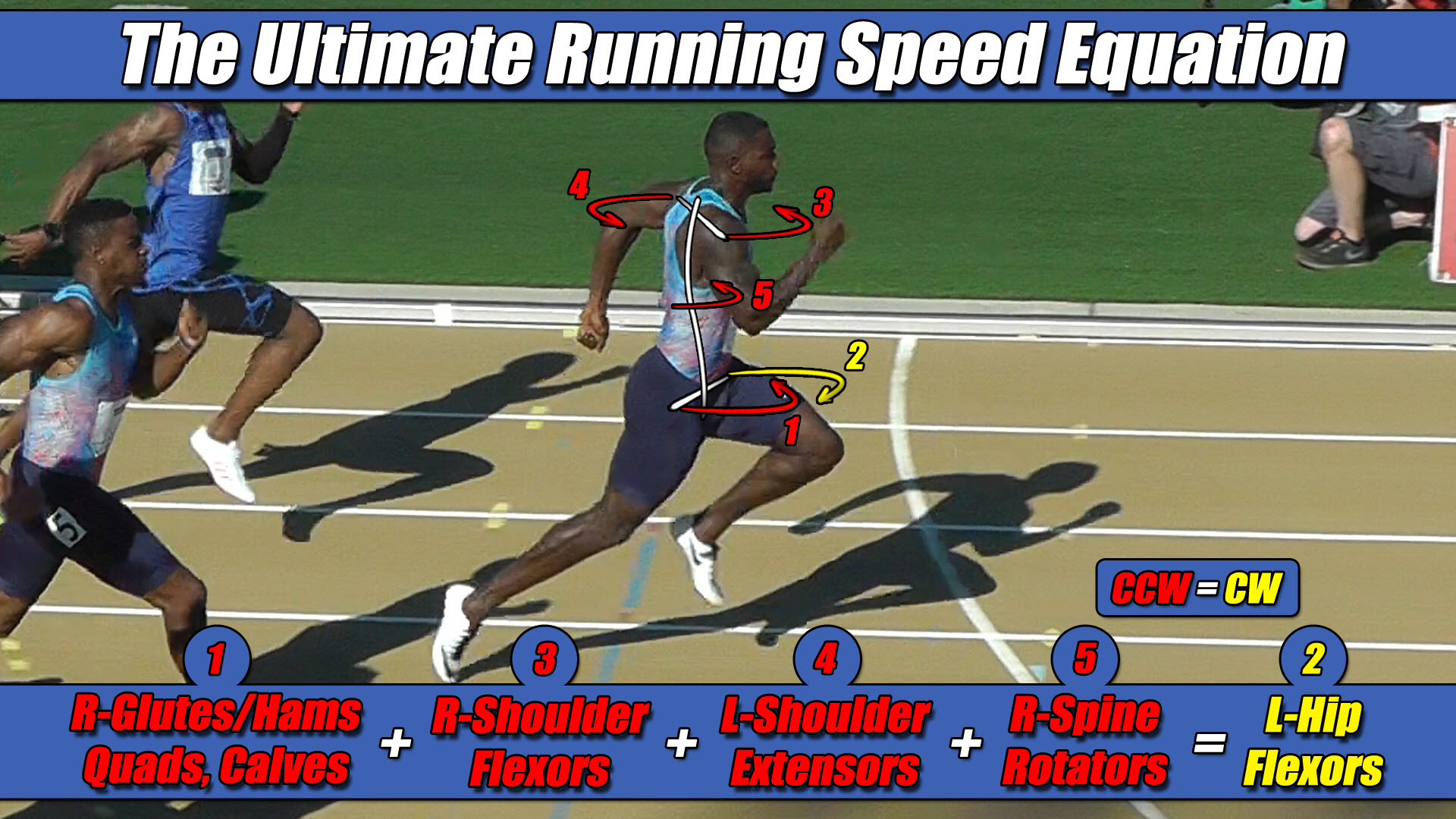 Left Hip Flexor Torque = CW. Everything Else CCW.
Decoding Torque Pattern 2 of 2
The athlete’s body has alternated to the other torque pattern. Repeat the process.
Apply the three steps to the runner in the figure below to determine the second of two torque patterns everyone shares for not just sprinting, but all human locomotion… walking. jogging, running:
- Identify the hip/thigh in flexion. This is what you need to key in at the very beginning. In the image below, it’s the right hip.
- Determine the torque direction of this hip/thigh based on the following constants: Right Leg = CCW Left Leg = CW. Therefore, Since we identified it was the right hip, we know it’s CCW.
- Everything else is going the other way. In this case, that means the pushing leg, left arm, right arm, torso = CW.

The second of two torque patterns everyone shares for not just sprinting, but all human locomotion… walking jogging, running is shown below:
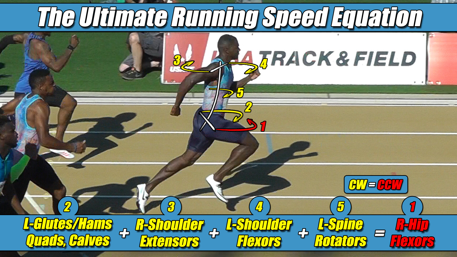
Right Hip Flexor Torque = CCW. Everything Else CW.
🏛️ Intellectual Property Notice & Legal Framework Boundaries
The Ultimate Running Speed Equation (URSE), along with its multi-axis pelvic torque constants and associated strength-balance profiling frameworks, represents the exclusive, proprietary intellectual property of Dr. Larry VanSuch. All rights reserved.
The clinical definitions outlined within this document function as established public prior art to protect the structural lineage of these discoveries.
Any unauthorized commercial exploitation, digital redistribution, or institutional replication of these geometric principles by outside entities without prior written consent is strictly prohibited.