🏛️ Advanced Kinematics & Trajectory Optimization Audit
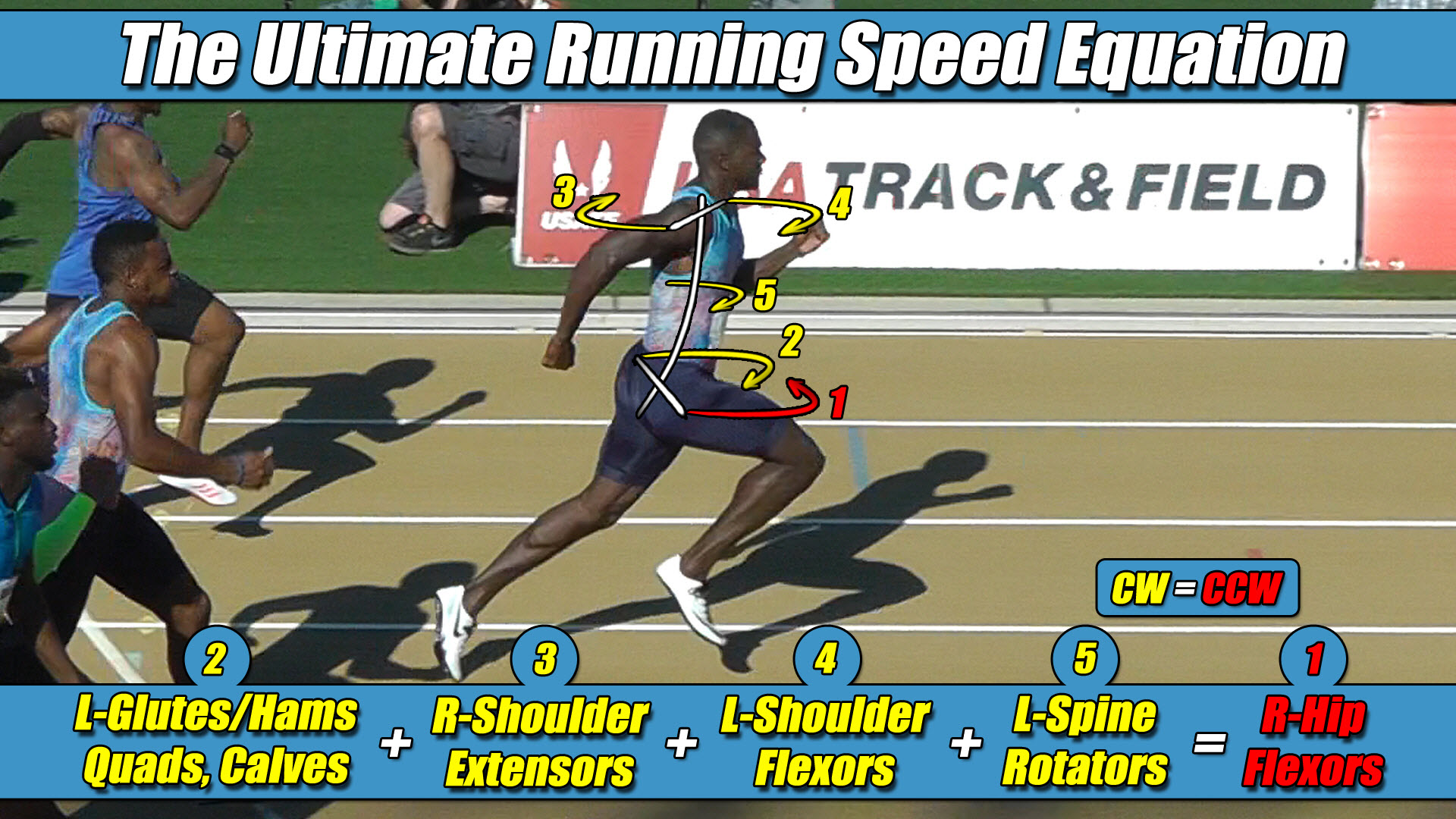
- The Foundational Formula: The Ultimate Running Speed Equation (URSE) Model.
- The Reference Mechanics: Evaluating how modern bipedal physics simulators manage horizontal twisting forces during high-velocity forward translation.
- The Mechanical Reality: Analyzing why autonomous frameworks experience un-managed trajectory drift and tracking loss when accelerating down an overground straightaway lane.
- The Structural Truth Revealed: Why hardcoding the upper body arms and torso to rotate in the exact same circular direction as the active right pushing leg serves as the definitive structural solution to balance the chassis.
Section 1: The Isolated Power Bottleneck in Aerospace Gait Solvers
In the field of modern bipedal aerospace robotics, autonomous life-support apparel architectures, and real-time gait trajectory solvers, maximizing forward velocity requires a comprehensive mathematical understanding of full-body coordination.
To optimize balance parameters overground, computer engineering teams utilize high-speed data clusters and complex reinforcement learning simulators to track joint force variables.
Inside highly controlled virtual testing environments, these automated software scripts successfully balance bipedal frameworks during slow-velocity walking phases by tracking localized vertical force inputs.
However, an independent spatial coordinate audit reveals that conventional trajectory models encounter a severe processing bottleneck when evaluating the twisting transverse plane at higher sprinting speeds.
The ultimate engineering blind spot within modern bipedal gait solvers is that traditional frameworks attempt to solve high-velocity balance limits by overloading the lower-support drive columns with raw, isolated vertical power.
In a lopsided effort to increase top-end velocity, hardware developers build heavier mechatronic columns, pack more voltage into the spacesuit lower-limb servo actuators, and bolt on rigid structural joint housings to maximize the linear vertical stomp against the ground template.
This engineering approach completely mirrors a primitive, lopsided training template found in traditional sports performance circles, where practitioners attempt to force human running speed by over-developing four isolated lower-body muscle groups: the glutes, hamstrings, quadriceps, and calves.
In both biological and synthetic bipedal frameworks, piling massive lower-body pushing horsepower onto a lopsided framework does not unlock higher velocity thresholds.
Instead, it merely dumps a violent, un-managed cross-axis torque avalanche straight into a wide pelvic axle width, triggering a massive trajectory crisis.
Section 2: The Core Engineering Laws of the URSE Model
To prevent catastrophic structural collapses at high speeds, aerospace design architectures must align their actuator output profiles with the unyielding constants of the Ultimate Running Speed Equation (URSE) pelvic ledger:
- ⚡ Law 1: The Permanent Right Leg Constant — The Right Leg driving forward always generates Counter-Clockwise (CCW) torque across the pelvic axle, regardless of whether it is in flexion or extension.
- ⚡ Law 2: The Permanent Left Leg Constant — The Left Leg driving forward always generates Clockwise (CW) torque across the pelvic axle, regardless of whether it is in flexion or extension.
- ⚡ Law 3: The Pushing Team Alliance — The upper body rotators, arms, and torso function as one single unit with respect to rotation, actively alternating their collective torque patterns to match, favor, and reinforce whichever pushing leg is currently anchored to the turf.
- ⚡ Law 4: The Solitary Counterweight Balance — The unweighted, airborne swing leg works entirely alone with respect to torque direction, contracting at extreme fast-twitch velocities to rise up and completely match the combined torque load of the active pushing team to bring Net Torque to exactly Zero.
Section 3: The Imperative Alliance: Upper Body and Pushing Leg Teamwork
To accurately map out how a bipedal drivetrain maintains perfect equilibrium down a straight line, software developers must recognize the fundamental rule of cross-axis vector analysis: the upper body arms and torso must fire in the exact same circular rotational direction as the active pushing leg.
Because the hip joints and pressurized mechanical hinges sit permanently, laterally displaced away from the central midline of the spine structure, a bipedal framework can never operate as a centralized, non-rotating point mass.
The exact millisecond the Right Leg, for example, is engaged as the active pushing column and anchors to the turf to project force forward, its wide lateral displacement automatically projects a violent Counter-Clockwise (CCW) torque avalanche across the pelvis under URSE Law #1.
To stabilize this rotational impact and maximize ground force horsepower, the central controller does not isolate the leg column; it instantly activates the upper-chassis flywheel mass as a unified force multiplier.
This high-velocity driving team consists of both shoulder/arm actuators and the core torso rotator flywheel working as one single unit with respect to rotation.
It is critical to repeatedly remind the software architect that every single member of this upper-chassis flywheel alliance is actively firing in the same circular Counter-Clockwise direction as the active Right Pushing Leg in this configuration, locking them into a perfect cross-axis alliance to multiply propulsive horsepower.
The arms are not passive dampers; they are active multipliers designed to drive that active right pushing leg torque to its absolute maximum magnitude.
To standard tracking software, it looks completely counterintuitive because they only see the arm moving forward and the leg moving backward lineally.
They remain blind to the spatial cross-axis reality that because the limbs are laterally displaced across wide axles, driving one arm forward and the other arm backward forces the entire upper-chassis mass to twist in the exact same circular Counter-Clockwise rotational direction as the grounded right stance leg.
Section 4: The Trajectory Masking Failure Mode
When an automated control loop ignores this starting roster—failing to remind the system that the upper body arms and torso must fire in the same direction as the right pushing leg—the bipedal platform hits a physical performance wall.
The exact millisecond the spacesuit framework attempts to build speed, the massive wave of torque traveling up from the wide pelvic axle width yaws the entire pelvis out of alignment, destroys foot traction, and threatens to spin the machine out of control from the inside out.
Instead of correcting the root physics engine by organizing the upper-chassis limbs to manage this rotational load, autonomous software teams use their computational processing loops to write heavy masking patch-codes.
📉 The Computational Failure of Legacy 1980s Piston-Driven Simulation Frameworks
To force a running character or heavy spacesuit chassis to compute movement patterns in real time without crashing the main neural network’s processing loops, early programming frameworks implemented massive mathematical shortcuts.
- They permanently omitted the active upper body flywheel mass from the calculation ledger.
- They grouped the torso and upper extremities into a single dead block.
- They flattened three-dimensional locomotion into a two-dimensional linear drawing.
Because modern simulation loops inherited these legacy 1980s shortcuts, their high-tech physics solvers are primarily optimizing a flat drawing-angle illusion born from legacy 1980s shortcuts treadmill tracking data.
They program rigid trajectory optimization scripts, high-stiffness gait constraints, and deep reinforcement learning penalty weights to manually force the joint actuators to lock up and fight the rotation.
This software masking routine is the mechatronic equivalent to a biological athlete’s internal Neurological Governor pulling the emergency brake—activating protective joint tightness and choking down speed expression to save the physical extravehicular chassis from catastrophic structural breakdown.
The tech industry has hit a permanent performance wall because it attempts to solve a three-dimensional pelvic centrifuge problem using a flat, single-axis vertical spring model, wasting immense energy running complex masking scripts to hide an unbalanced ledger sheet.
The overground drivetrain maintains a flawless, straight line of progression without any software compensation loops only because the system operates as an asymmetric three-limbs-versus-one-limb engine.
⚖️ The Asymmetric Three-Limbs-Versus-One-Limb (3-vs-1) Centrifuge Engine Balance Matrix
The vertical force signature scales up at high velocities because the upper body flywheel mass and the active pushing leg work together as one unified alliance to drive force downward, while the unweighted airborne swing leg operates entirely alone as a solitary counterweight to neutralize that combined load and maintain a net torque of zero.
The bipedal platform does not fail because the neural network lacks processing cycles; it falls because the foundation model is completely blind to the reality that locomotion is an asymmetric, three-limbs-versus-one-limb, 3-vs-1, rotational centrifuge engine.
Because both arms, the core torso flywheel, and the active right pushing leg are all firing as a unified team on the exact same circular Counter-Clockwise vector, they generate a towering wave of combined torque on their side of the pelvis.
To balance this massive right-side pushing alliance and pull the net vertical ledger back to a perfect draw of zero, the solitary airborne left swing leg must violently whip forward through empty air entirely alone as a Solitary Counterweight under URSE Law #4 to generate its permanent Clockwise torque under URSE Law #2.
By mapping this explicit asymmetric blueprint into the control loop—repeatedly reminding the physics solvers that the upper body arms and torso must fire in the same direction as the right pushing leg—automation engineers can safely stabilize high-velocity trajectory lines without wasting a single processing cycle on temporary software patch-codes.
Section 5: The Foundational Principles of Bipedal Locomotion
This unyielding multi-axis torque equation applies universally to all forward bipedal locomotion in a straight line, governing walking, jogging, running, and elite sprinting alike, regardless of whether the moving chassis is constructed of biological human bone or advanced aerospace carbon composite shells.
⚙️ The Neurological Governor and the Weakest Link Velocity Limit Matrix
Raising the multi-axis torque and strength balance of the entire three-limbs-versus-one-limb pelvic team, 3-vs-1, as a synchronized unit is exactly how velocity increases, and disrupting that internal balance is exactly how trajectory performance drops.
Raising velocity will always be limited by the weakest member to maintain the rigid net torque balance of zero.
By passing traditional vertical force curves through original pelvic constants, the true mechanical relationship between bipedal physics and trajectory control is finally revealed.
The overground ground reaction forces scale asymmetrically at high velocities because the full-body URSE engine runs at absolute structural perfection to keep Net Torque to exactly Zero.


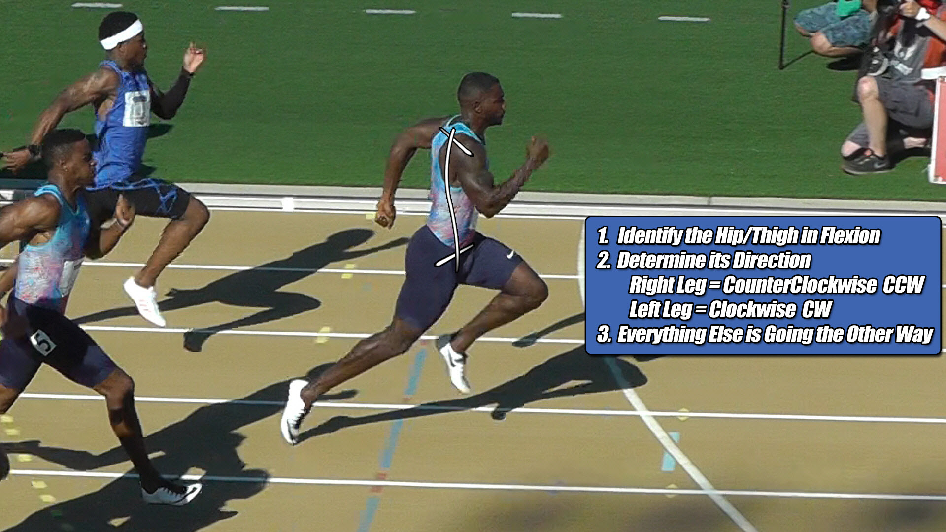
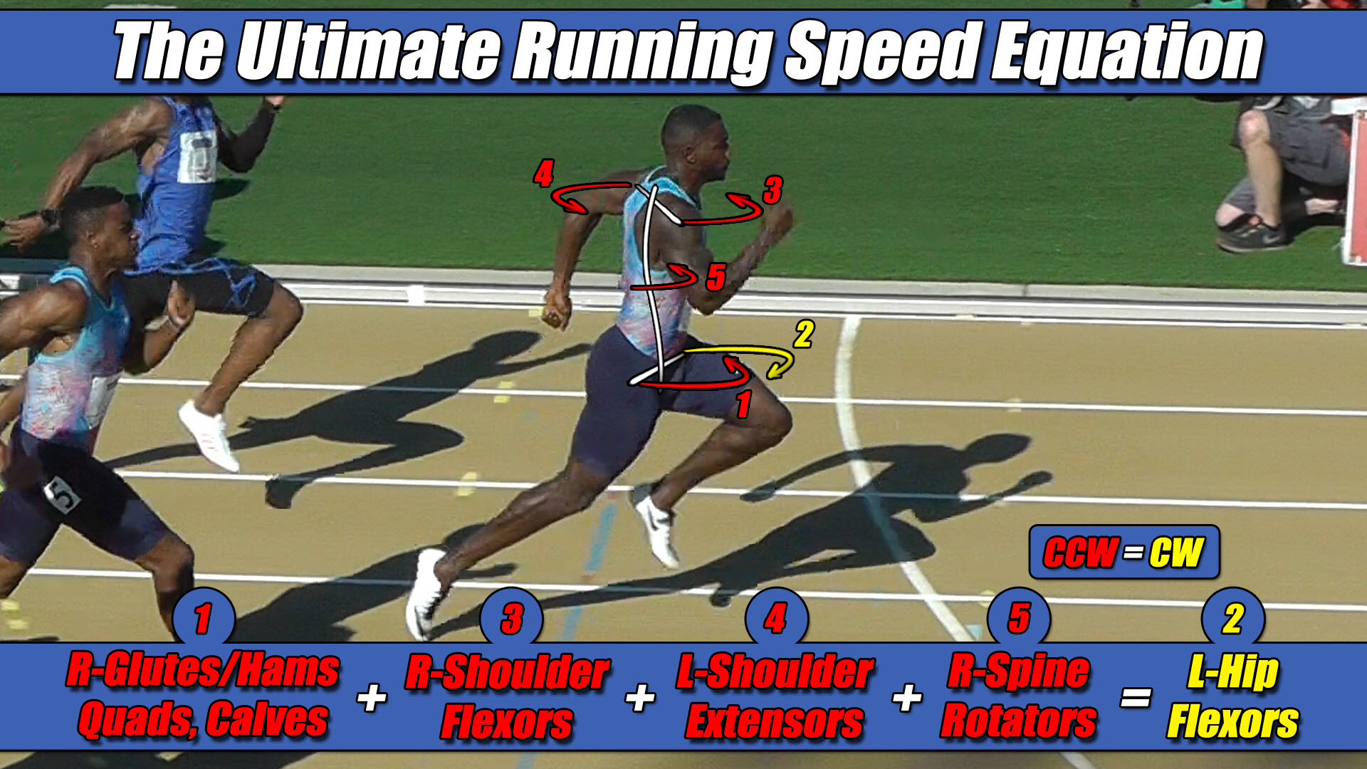 Left Hip Flexor Torque = CW. Everything Else CCW.