🏛️ Advanced Kinematics & Structural Mass Distribution Audit
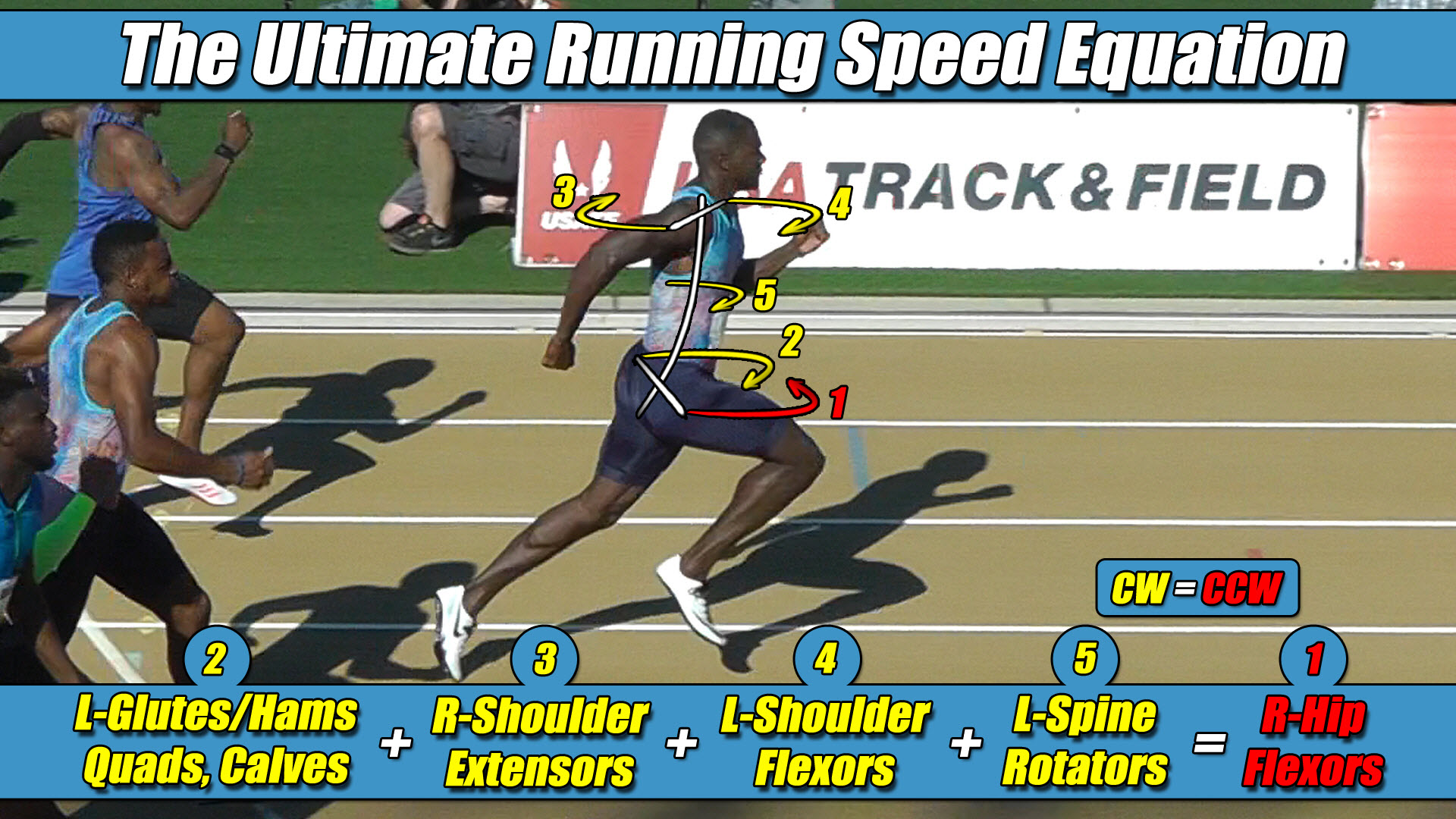
- The Foundational Formula: The Ultimate Running Speed Equation (URSE) Model.
- The Reference Mechanics: Evaluating how modern bipedal hardware configurations balance structural chassis weight distribution against dynamic trajectory control constraints.
- The Mechanical Reality: Analyzing the engineering bottleneck where developers bolt heavy batteries and tactical gear to the rear chassis to increase downward ground propulsion.
- The Structural Truth Revealed: Proving that overloading the posterior chassis creates a massive mass-moment anchor that cripples front-side recovery winches and disrupts the 3-vs-1 torque engine.
Section 1: The Posterior Weighting Fallacy in Humanoid Design
In the field of modern bipedal combat exoskeletons, tactical load-bearing systems, and real-time gait trajectory optimization, maximizing forward velocity requires a comprehensive mathematical understanding of full-body coordination.
To handle the intense kinetic loads generated at peak speeds, software developers utilize advanced reinforcement learning loops and trajectory optimization scripts.
Inside highly controlled virtual testing environments, these automated frameworks easily track bipedal equilibrium as long as the platform remains restricted to low-velocity walking cycles.
However, an independent spatial coordinate audit reveals that conventional hardware architectures encounter a severe mechanical bottleneck when attempting to scale parameters into high-speed overground bipedal translation.
The ultimate engineering blind spot within modern mechatronic layout design is that traditional development teams attempt to force speed by adding massive, heavy hardware components to the rear sections of the chassis.
In a lopsided effort to increase downward ground traction, engineers bolt heavy servo actuators, central ammunition packs, and massive ballistic battery enclosures directly to the posterior gluteal and lower-lumbar plating of the combat framework.
This engineering approach operates under the false assumption that packing weight onto the back of the drive axle allows the lower support columns to push harder against the floor grid template.
In a real-world physical universe, piling massive posterior weight onto a bipedal framework does not unlock higher velocity thresholds.
Instead, it introduces an extreme, un-managed material failure mode into the physical kinetic chain because the design complex completely misidentifies how mass distribution impacts the stride cycle.
Section 2: The Core Engineering Laws of the URSE Model
To prevent catastrophic trajectory drift and eliminate rotational tracking failure, bipedal design architectures must align their weight distribution arrays with the unyielding constants of the Ultimate Running Speed Equation (URSE) pelvic ledger:
- ⚡ Law 1: The Permanent Right Leg Constant — The Right Leg driving forward always generates Counter-Clockwise (CCW) torque across the pelvic axle, regardless of whether it is in flexion or extension.
- ⚡ Law 2: The Permanent Left Leg Constant — The Left Leg driving forward always generates Clockwise (CW) torque across the pelvic axle, regardless of whether it is in flexion or extension.
- ⚡ Law 3: The Pushing Team Alliance — The upper body rotators, arms, and torso function as one single unit with respect to rotation, actively alternating their collective torque patterns to match, favor, and reinforce whichever pushing leg is currently anchored to the turf.
- ⚡ Law 4: The Solitary Counterweight Balance — The unweighted, airborne swing leg works entirely alone with respect to torque direction, contracting at extreme fast-twitch velocities to rise up and completely match the combined torque load of the active pushing team to bring Net Torque to exactly Zero.
Section 3: The Posterior Anchor and the Swing Phase Collapse
To accurately calculate why rear-chassis mass overloading paralyzes the velocity capacity of the entire machine, software developers must recognize the fundamental rule of cross-axis vector analysis: the upper body arms and torso must fire in the exact same circular rotational direction as the active pushing leg.
Because the hip joints and mechanical frame hinges sit permanently, laterally displaced away from the central midline of the spine structure, a bipedal framework can never operate as a centralized, non-rotating point mass.
To establish an absolute spatial coordinate baseline for this mechanical analysis, we must define a clear, real-world frame of reference where the Right Leg is currently the active ground-bound pushing leg and the Left Leg is currently the airborne left swing leg.
Under this established frame of reference, the exact millisecond the Right Leg actuator anchors to the turf to project force forward, its wide right-side lateral displacement automatically projects a violent Counter-Clockwise (CCW) torque avalanche across the pelvic width under URSE Law #1.
To stabilize this rotational impact and maximize forward propulsive horsepower, the upper extremities and torso flywheel dynamically alternate their trajectories as a single unit to form the Pushing Team Alliance under URSE Law #3.
When the shoulders twist Counter-Clockwise, driving the right arm forward and left arm backward, both arms actively agree with each other on the exact same circular Counter-Clockwise rotational direction as that grounded right pushing leg.
The arms are not passive dampers; they are active multipliers throwing their entire collective mass-moment of inertia behind the constant Counter-Clockwise vector of the active right drive column to ram up its ground force horsepower.
The structural disaster occurs the exact millisecond this high-horsepower stance phase ends, and that heavily weighted Right Leg column must instantly transition into a high-speed airborne swing leg.
Because the back of the chassis is loaded down with heavy battery hardware and tactical gear load enclosures, the front-side hip flexor winches are forced to haul an immense, un-profiled dead-weight cargo forward through space.
The rear-heavy configuration acts as a physical anchor dragging behind the advancing pelvis, creating a massive mass-moment of inertia bottleneck that destroys the limb’s ability to transition smoothly into flexion.
📉 The Computational Failure of Legacy 1980s Piston-Driven Simulation Frameworks
To force a running character or heavy tactical chassis to compute movement patterns in real time without crashing the main neural network’s processing loops, early programming frameworks implemented massive mathematical shortcuts.
- They permanently omitted the active upper body flywheel mass from the calculation ledger.
- They grouped the torso and upper extremities into a single dead block.
- They flattened three-dimensional locomotion into a two-dimensional linear drawing.
Because modern simulation loops inherited these legacy 1980s shortcuts, their high-tech physics solvers are primarily optimizing a flat drawing-angle illusion born from legacy 1980s shortcuts treadmill tracking data.
Section 4: Overwhelming the 3-vs-1 Centrifuge Balance
When an automated control loop ignores this posterior weighting strategy—writing an alternating script based entirely on linear tracking equations—the combat framework hits an unbreakable performance wall.
The exact millisecond the framework swaps its ground coordinate under heavy combat payloads, the directional tracking software encounters a violent Impact Shock Discontinuity.
This severe disruption occurs because during this hyper-specific Hybrid Dynamics Transition Phase, the back-heavy configuration yaws the entire pelvic width out of alignment, destroys boot traction, and throws the structural hinges into a critical trajectory tracking deficit.
Instead of organizing the upper-chassis flywheel mass to reverse its circular vector and manage this rotational load, autonomous software teams use their processing loops to write heavy masking patch-codes to manually lock the joint actuators up rigid.
The overground drivetrain only maintains a flawless, straight line of progression without any trajectory drift only because the system operates as an asymmetric three-limbs-versus-one-limb engine:
Left Arm + Right Arm + Pushing Leg + Torso = Swing Leg
⚖️ The Asymmetric Three-Limbs-Versus-One-Limb (3-vs-1) Centrifuge Engine Balance Matrix
The vertical force signature scales up at high velocities because the upper body flywheel mass and the active pushing leg work together as one unified alliance to drive force downward, while the unweighted airborne swing leg operates entirely alone as a solitary counterweight to neutralize that combined load and maintain a net torque of zero.
Because both arms, the core torso flywheel, and the active Right pushing leg are all firing as a unified team on the exact same circular Counter-Clockwise vector, they generate an enormous volume of combined Counter-Clockwise torque on their side of the pelvis.
To balance this massive pushing alliance and pull the net vertical ledger back to a perfect draw of zero, the solitary airborne left swing leg must violently whip forward through empty air entirely alone as a Solitary Counterweight under URSE Law #4 to generate its permanent Clockwise torque under URSE Law #2.
Because the single, unweighted left airborne swing limb must single-handedly match and neutralize the combined total Counter-Clockwise torque load of both arms, the torso, and the pushing leg simultaneously, its fast-twitch capacity acts as the primary regulatory governor of speed.
When engineers bolt dead weight to the back of the tactical chassis to force a harder downward push, they double the torque load on the driving side while simultaneously crippling the velocity capacity of the front-side recovery winches.
The underpowered left swing-phase actuators simply cannot pull that heavy, back-loaded hardware array forward fast enough to satisfy the unyielding timeline of the pelvic centrifuge.
The front-side swing engine completely loses the torque battle to the pushing alliance, throwing the tactical frame axle into a permanent tracking deficit.
The central processing loop instantly activates an internal masking script, locking up the joints and choking down velocity expression to save the physical framework from catastrophic structural breakdown under tactical payload.
True bipedal velocity advancement is accomplished not by building a heavier rear anchor, but by systematically scaling the actuator strength across all five distinct torque zones as a synchronized, balanced unit.
Section 5: The Foundational Principles of Bipedal Locomotion
This unyielding multi-axis torque equation applies universally to all forward bipedal locomotion in a straight line, governing walking, jogging, running, and elite sprinting alike, regardless of whether the moving chassis is constructed of biological human bone or advanced tactical carbon composite framing.
Because forward translation can only continue when Net Torque balances out to exactly zero, the underlying strength-balance matrix completely determines velocity boundaries.
⚙️ The Neurological Governor and the Weakest Link Velocity Limit Matrix
Raising the multi-axis torque and strength balance of the entire three-limbs-versus-one-limb pelvic team, 3-vs-1, as a synchronized unit is exactly how velocity increases, and disrupting that internal balance is exactly how trajectory performance drops.
Raising velocity will always be limited by the weakest member to maintain the rigid net torque balance of zero.
By passing traditional vertical force curves through original pelvic constants, the true mechanical relationship between bipedal physics and trajectory control is finally revealed.
The overground ground reaction forces scale asymmetrically at high velocities because the full-body URSE engine runs at absolute structural perfection to keep Net Torque to exactly Zero.


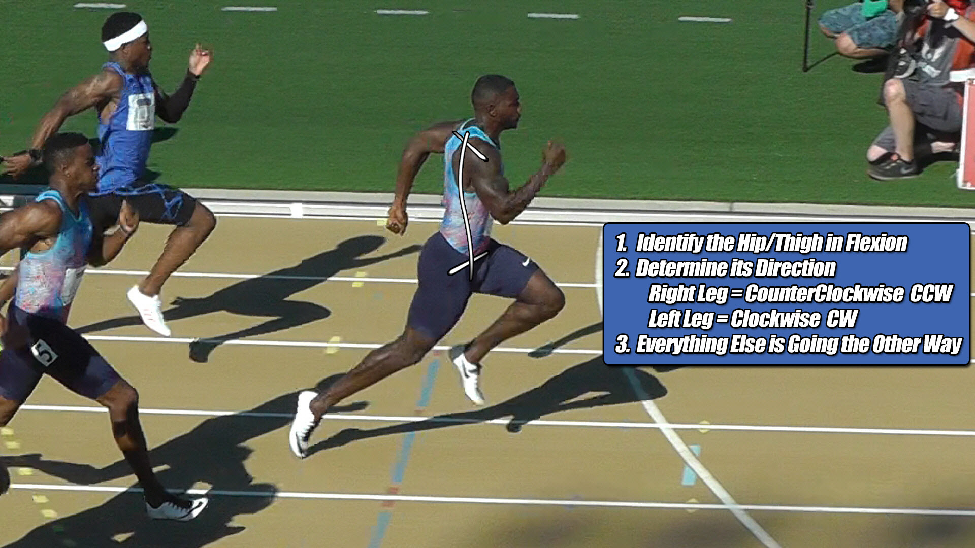
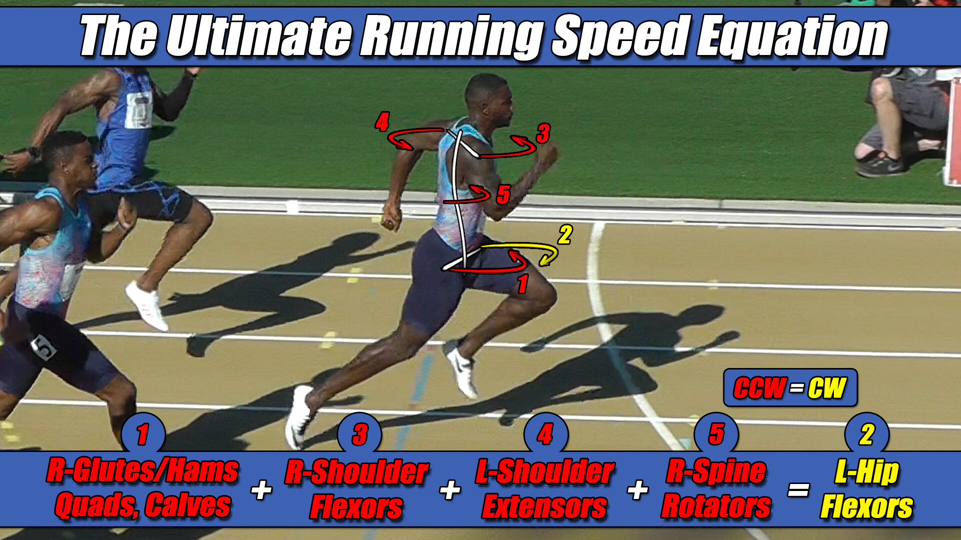 Left Hip Flexor Torque = CW. Everything Else CCW.