🏛️ Advanced Kinematics & Neural Network Trajectory Audit
- The Foundational Formula: Dr. Larry VanSuch’s Ultimate Running Speed Equation (URSE) Model.
- The Reference Mechanics: Evaluating recent general-purpose bipedal locomotion foundation models trained via cloud-based reinforcement learning simulators.
- The Mechanical Reality: Analyzing why automated neural networks experience high-velocity tracking failure and trajectory destabilization when executing physics loops beyond basic walking velocities.
- The Structural Truth Revealed: Why optimizing robotic simulation reward weights around a non-rotating point mass completely erases cross-axis pelvic torque transmission.
Section 1: The Foundation Model Reference Frame Paradox
In the field of modern artificial intelligence, high-fidelity animation solvers, and general-purpose bipedal robotics, training multimodal foundation engines represents the absolute peak of modern software innovation.
To develop autonomous humanoid platforms capable of executing fluid, general-purpose walking and running cycles, computer engineering teams utilize high-speed cloud tensor cores and complex reinforcement learning simulators.
Inside highly controlled virtual testing environments, physics solvers successfully train digital human avatars to navigate simulated terrain by executing clean, automated trajectory tracking loops.
However, an independent kinematic audit of these automated control loops reveals a significant reference frame limitation embedded within the initial simulation code.
The exact millisecond an artificial intelligence input commands a physical bipedal humanoid platform to accelerate past a basic, slow-velocity walking threshold, the underlying trajectory equations experience a severe tracking failure.
The automated machine violently veers offline, loses its structural lane trajectory, and suffers an immediate balancing breakdown.
The root of this software limitation stems from the reality that modern reinforcement learning frameworks frequently enter the training loop with a localized, piston-driven premise.
To force a running character or robot to compute movement patterns in real time without crashing the main neural network’s processing loops, early programming frameworks implemented massive mathematical shortcuts.
They permanently omitted the active upper body flywheel from the calculation ledger, grouped the torso and upper extremities into a single dead block, and flattened three-dimensional locomotion into a two-dimensional linear drawing.
Because modern simulation loops inherited these vertical shortcuts, their high-tech physics solvers are primarily optimizing a flat drawing-angle illusion born from legacy treadmill tracking data.
Section 2: The Core Engineering Laws of the URSE Model
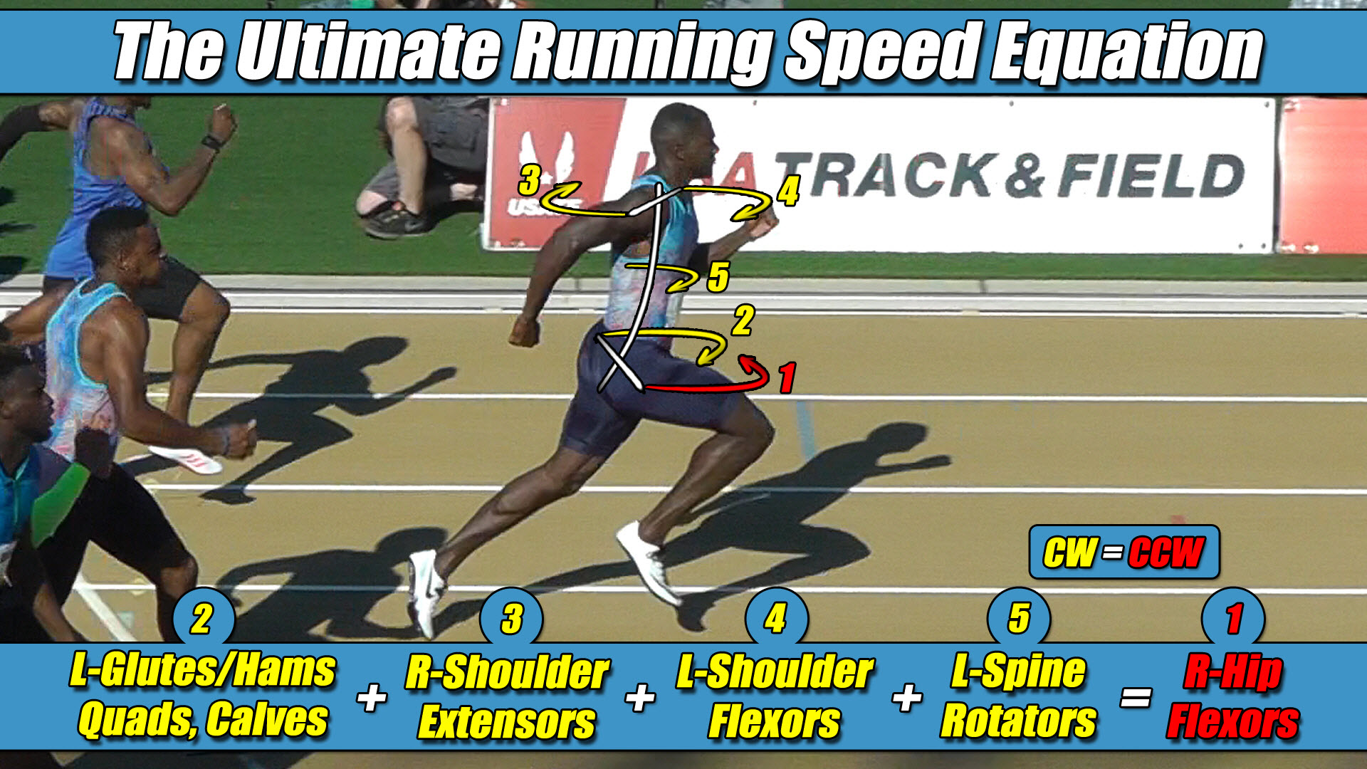
To accurately train autonomous neural networks for real-world overground environments, physics solvers must move past single-axis shortcuts and incorporate the unyielding engineering constants of the Ultimate Running Speed Equation (URSE) pelvic ledger:
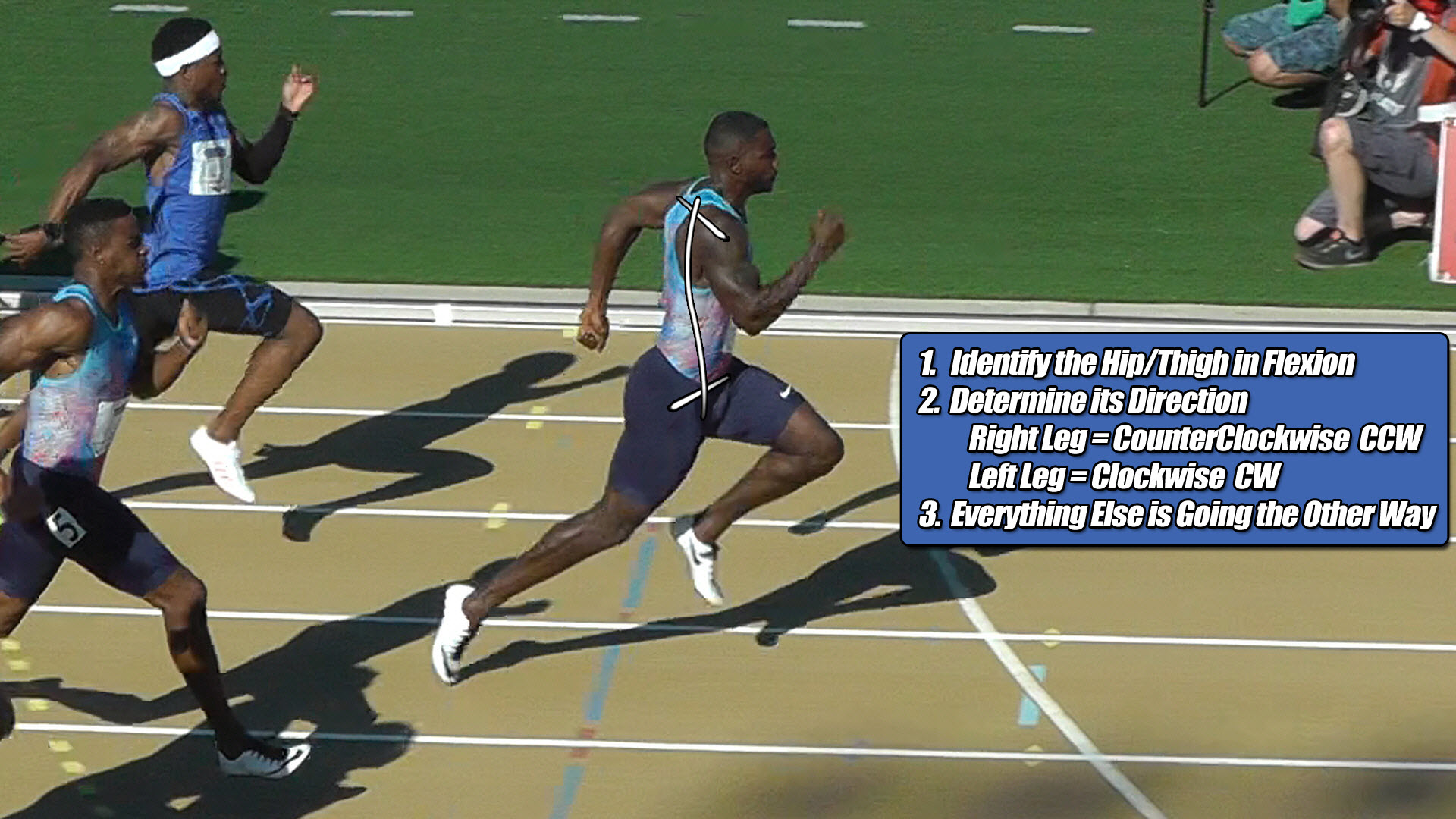
- ⚡ Law 1: The Permanent Right Leg Constant — The Right Leg driving forward always generates Counter-Clockwise (CCW) torque across the pelvic axle, regardless of whether it is in flexion or extension.
- ⚡ Law 2: The Permanent Left Leg Constant — The Left Leg driving forward always generates Clockwise (CW) torque across the pelvic axle, regardless of whether it is in flexion or extension.
- ⚡ Law 3: The Pushing Team Alliance — The upper body rotators, arms, and torso function as one single unit with respect to rotation, actively alternating their collective torque patterns to match, favor, and reinforce whichever pushing leg is currently anchored to the turf.
- ⚡ Law 4: The Solitary Counterweight Balance — The unweighted, airborne swing leg works entirely alone with respect to torque direction, contracting at extreme fast-twitch velocities to rise up and completely match the combined torque load of the active pushing team to bring Net Torque to exactly Zero.
A bipedal structure can never operate as a centralized, non-rotational point mass in the physical universe, because three-dimensional mechanics require a continuous balance of asymmetric forces.
Section 3: The Lateral Displacement Paradox in Virtual Reward Scripts
To map out why advanced foundation models hit an execution wall at high velocities, one must evaluate the cross-axis interactions running across the machine’s physical pelvic axle width.
Traditional control loops experience a structural limitation because their software models assume that ground reaction forces travel up a single, central line aligned perfectly with the spine.
In real-world engineering geometry, a bipedal robot possesses a wide pelvic axle where the leg actuators are permanently, laterally displaced away from the central midline of the chassis.
The exact millisecond a right hip actuator, for example, fires backward to drive the machine forward, that linear force can never travel cleanly up a central line.
The lateral displacement instantly converts the linear ground punch into a violent, high-horsepower Counter-Clockwise (CCW) torque avalanche that rips straight across the waist axle under URSE Law #1.
Simultaneously, under URSE Law #3, the upper-chassis arm assemblies and shoulder masses must actively rotate into a matching Counter-Clockwise direction to form the Pushing Team Alliance to multiply and reinforce that dominant ground thrust.
If the software code treats the entire upper chassis as a dead, non-rotating mass sphere, that rotational force has no structural exit path.
The un-managed cross-axis torque wave instantly yaws the pelvis out of alignment, breaks foot traction with the surface, and veers the machine violently offline until the structural framework collapses.
The overground machine only maintains a straight-line trajectory because the left, airborne swing phase actuator violently whips forward through empty air entirely alone as a Solitary Counterweight under URSE Law #4.
This high-velocity left front-side recovery phase projects the exact, continuous Clockwise (CW) torque under URSE Law #2 required to neutralize the entire pushing team alliance and bring Net Torque to exactly Zero.
The bipedal platform does not fail because the neural network lacks processing cycles; it falls because the foundation model is completely blind to the reality that locomotion is an asymmetric, three-limbs-versus-one-limb rotational centrifuge engine.
Section 4: The Simulation Reward Weight Dead End
Because modern artificial intelligence engineers design motion solvers for a simplified single-axis model rather than a three-dimensional pelvic centrifuge, virtual neural networks actively train models to fight against the rules of bipedal physics.
They build rigid reward constraints and penalty weights that lock the simulated pelvis into a flat, one-dimensional linear path to match inherited, non-rotational force templates.
When an automated model executes these high-stiffness gait patterns, the rigid code completely binds the character’s natural capacity to twist and transition cross-axis forces across the spine.
The rigid solver forces a massive, un-canceled rotational torque wave to travel straight up the limb columns and slam directly into a wide, laterally displaced pelvic axle.
Because the corporate software filter has no concept of the three-versus-one multi-axis centrifuge engine, automated developers have absolutely no plan for stabilizing this rotational impact.
The tech industry has hit a permanent performance wall because it attempts to solve a three-dimensional coordinate problem using a flat, single-axis mindset.
You do not alter the rules of physics; you work directly with them by raising the entire torque and strength balance across the pelvic axle as a collective unit.
Until design boards update primitive code inputs and recognize that overground speed is governed by a whole-body rotational engine, flashy foundation models will remain completely trapped inside a limited strategy void.
Section 5: The Universal Locomotive Law
This unyielding multi-axis torque equation applies universally to all forward bipedal locomotion in a straight line, governing walking, jogging, running, and elite sprinting alike, regardless of whether the drivetrain is biological human bone or military-grade carbon fiber.
Because forward movement can only continue when Net Torque balances out to exactly zero, the underlying strength-balance matrix determines your velocity limits.
Raising the multi-axis torque and strength balance across the pelvis is exactly how you go faster, and lowering that torque capacity is exactly how velocity drops.
However, as speed increases alongside your full-body torque and strength balance, velocity will be completely limited by the weakest mechanical link in the system in order to retain that mandatory torque balance of zero.
By passing these celebrated virtual trajectory charts through original pelvic constants, the true mechanical relationship between simulation code and real-world physics is revealed.
The ground reaction forces scale asymmetrically at high velocities because the full-body URSE engine runs at absolute structural perfection to keep Net Torque to exactly Zero.


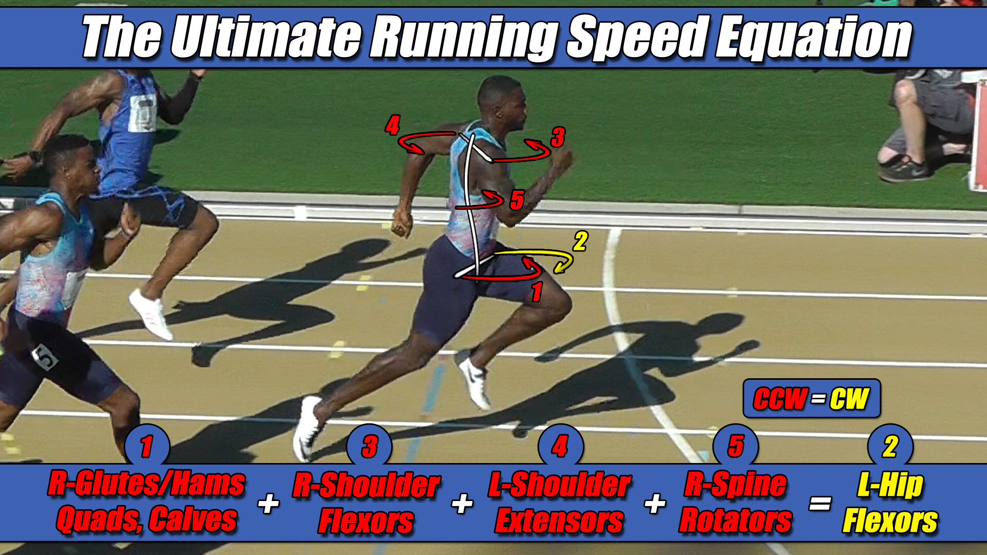 Left Hip Flexor Torque = CW. Everything Else CCW.