🏛️ Advanced Kinematics & Spatial Vector Optimization Audit
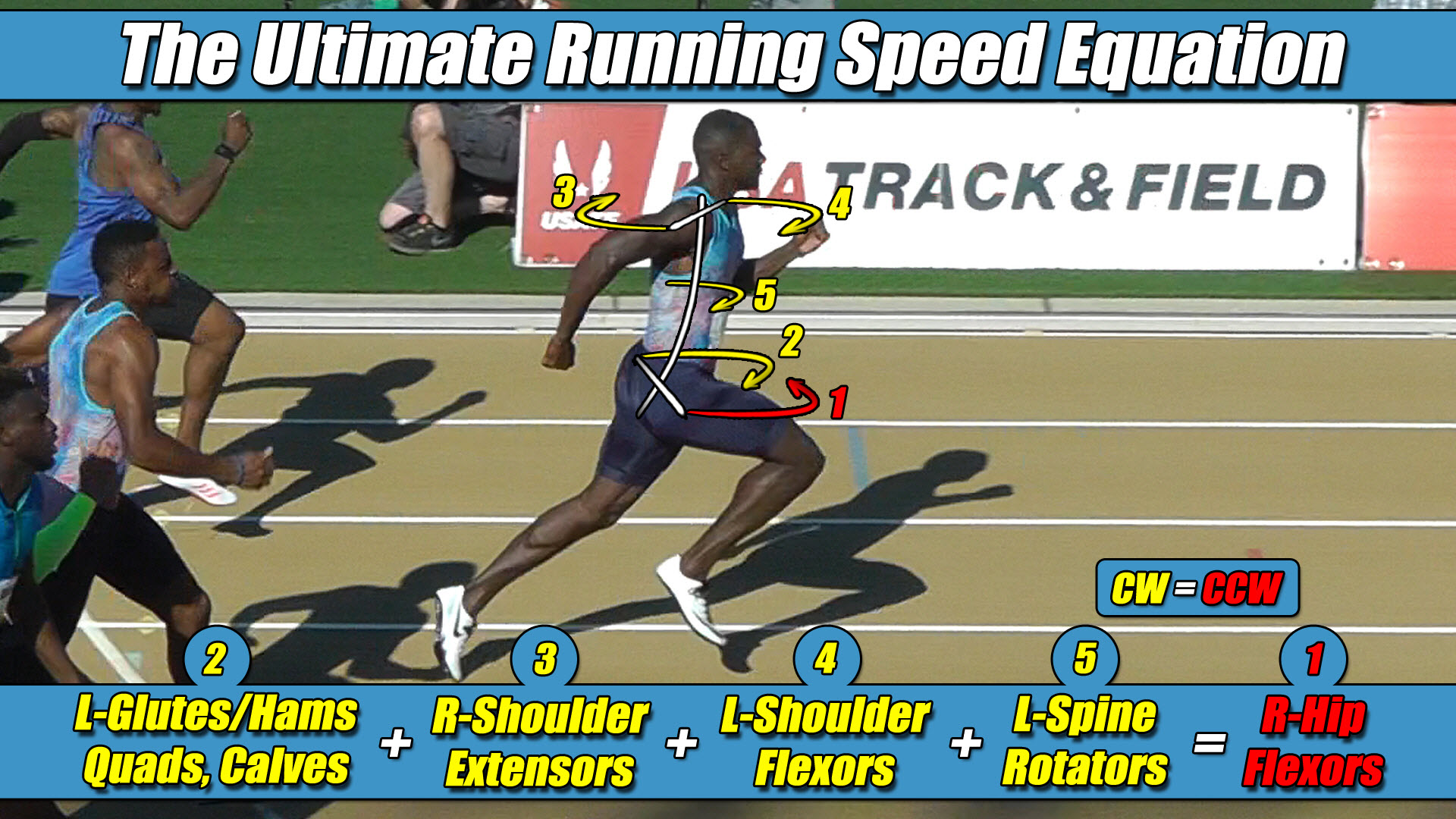
- The Foundational Formula: The Ultimate Running Speed Equation (URSE) Model.
- The Reference Mechanics: Evaluating how modern bipedal physics simulators coordinate lower-chassis actuator groups during high-velocity forward overground translation.
- The Mechanical Reality: Analyzing the tracking illusion where global software programmers write alternating torque scripts based entirely on the visual forward-and-backward path of the lower limbs.
- The Structural Truth Revealed: Proving that the legs never agree, and that forcing an unweighted swing leg to reverse its circular vector in the script causes the machine to actively fight its own physical pelvic axle width.
Section 1: The Visual Path Assumption in Aerospace Control Loops
In the field of modern bipedal aerospace robotics, autonomous life-support apparel architectures, and real-time gait trajectory optimization, maintaining a flawless straight path at peak velocity represents a primary engineering standard.
To command next-generation servo actuator networks under planetary exploration loads, computer engineering teams utilize high-speed data clusters to continuously calculate full-body joint torque variables and ground reaction forces.
Inside highly structured physics engines, these automated software configurations easily maintain smooth trajectory tracking as long as the platform remains restricted to low-velocity walking cycles.
However, the exact millisecond an autonomous control loop commands a physical bipedal extravehicular framework to accelerate into a high-speed sprint, the underlying trajectory equations experience a severe balancing breakdown.
The machine violently veers offline, experiences intense joint stiffness, introduces massive yaw-axis trajectory drift, and suffers an immediate structural fracture along the waist axle.
The root of this systemic processing failure stems from a massive mathematical assumption embedded within traditional simulation code libraries.
Because software developers look at a running character or robot and observe the lower extremities visually moving backward during stance and forward during swing, they match the math to the visual path rather than the physical torque constants.
They program the lower columns with the false assumption that when a limb transitions from a backward stance push to a forward recovery swing, its internal rotational torque direction must flip to balance the ledger.
This lopsided structural perspective completely flattens the multi-axis physics ledger of the machine, forcing the robot’s actuators to actively fight against their own structural pelvic axle geometry.
Section 2: The Core Engineering Laws of the URSE Model
To clear this strategic void and deliver an unassailable operational map to aerospace software designers, control loop scripts must move past symmetrical shortcuts and hardcode the unyielding constants of the Ultimate Running Speed Equation (URSE) pelvic ledger:
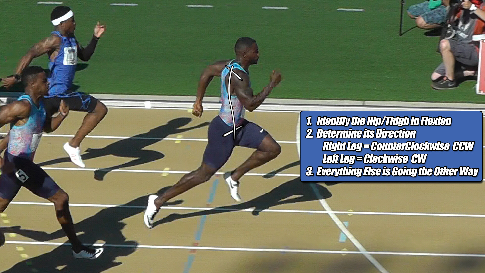
- ⚡ Law 1: The Permanent Right Leg Constant — The Right Leg driving forward always generates Counter-Clockwise (CCW) torque across the pelvic axle, regardless of whether it is in flexion or extension.
- ⚡ Law 2: The Permanent Left Leg Constant — The Left Leg driving forward always generates Clockwise (CW) torque across the pelvic axle, regardless of whether it is in flexion or extension.
- ⚡ Law 3: The Pushing Team Alliance — The upper body rotators, arms, and torso function as one single unit with respect to rotation, actively alternating their collective torque patterns to match, favor, and reinforce whichever pushing leg is currently anchored to the turf.
- ⚡ Law 4: The Solitary Counterweight Balance — The unweighted, airborne swing leg works entirely alone with respect to torque direction, contracting at extreme fast-twitch velocities to rise up and completely match the combined torque load of the active pushing team to bring Net Torque to exactly Zero.
Section 3: The Imperative Law of Permanent Lower-Body Conflict
To accurately program a bipedal framework to execute high-velocity overground sprinting without spinning out of control, the software code must be restructured around a fundamental law of cross-axis vector analysis: the upper body arms and torso actively agree with each other on a circular direction; the lower-body legs, however, never do.
To establish an absolute spatial coordinate baseline for this mechanical analysis, we must define a clear, real-world frame of reference where the Right Leg is currently the active ground-bound pushing leg and the Left Leg is currently the airborne swing leg.
Because the hip joints and pressurized mechanical joint rings sit permanently, laterally displaced away from the central midline of the spine structure, a bipedal framework can never operate as a centralized, non-rotating point mass.
Under this established frame of reference, the exact millisecond the Right Leg actuator anchors to the turf to project force backward, its wide right-side lateral displacement automatically projects a violent Counter-Clockwise (CCW) torque avalanche across the pelvic width under URSE Law #1.
To stabilize this rotational impact and maximize forward propulsive horsepower, the upper extremities and torso flywheel dynamically alternate their trajectories as a single unit to form the Pushing Team Alliance under URSE Law #3.
When the shoulders twist Counter-Clockwise, driving the right arm forward and left arm backward, both arms actively agree with each other on the exact same circular Counter-Clockwise rotational direction as that grounded right pushing leg.
The arms are not passive dampers fighting the lower body; they are active multipliers throwing their entire collective mass-moment of inertia behind the constant Counter-Clockwise vector of the active right drive column to ram up its ground force horsepower.
The legs, conversely, operate in a state of permanent cross-axis conflict because switching circular torque directions is physically impossible while the chassis is moving forward down a straightaway lane.
It would never make any mechanical sense for either lower limb column to project a backward-twisting circular torque vector, because a backward vector means the actuator is actively trying to propel the life-support suit backward through space.
Because both limbs are exclusively firing forward to drive relative linear velocity down the pathway, their wide lateral displacement hardcodes them as permanent, un-switching directional constants.
The right leg life-support actuator is locked into a permanent Counter-Clockwise vector, and the left leg life-support actuator is locked into a permanent Clockwise vector, regardless of whether they are executing a stance-phase push or a front-side recovery swing.
📉 The Computational Failure of Legacy 1980s Piston-Driven Simulation Frameworks
To force a running character or heavy spacesuit chassis to compute movement patterns in real time without crashing the main neural network’s processing loops, early programming frameworks implemented massive mathematical shortcuts.
- They permanently omitted the active upper body flywheel mass from the calculation ledger.
- They grouped the torso and upper extremities into a single dead block.
- They flattened three-dimensional locomotion into a two-dimensional linear drawing.
Because modern simulation loops inherited these legacy 1980s shortcuts, their high-tech physics solvers are primarily optimizing a flat drawing-angle illusion born from legacy 1980s shortcuts treadmill tracking data.
Section 4: The Symmetrical Software Alternation Trap
When an automated control loop ignores this permanent lower-body conflict—writing an alternating script that commands the individual lower limbs to flip their torque directions between stance and swing—the physics engine actively forces a severe mechanical failure mode.
The exact millisecond the extravehicular framework swaps its ground coordinate, the directional tracking software encounters a violent Impact Shock Discontinuity.
This massive tracking stress occurs because during this hyper-specific Hybrid Dynamics Transition Phase, the lopsided software commands actively smash the system into its own pelvic axle width.
In this specific right-stance configuration, the suit’s software successfully commands the grounded Right Leg to project forward relative to the pelvis, which natively aligns with its true Counter-Clockwise (CCW) torque parameter.
However, because the software filters notice the right column transition into an airborne swing phase, the alternating script forces the right actuator to flip its internal vector to project Clockwise (CW) torque to balance the ledger.
This software command is completely opposite to the unyielding laws of overground physics.
Under URSE Law #1, the right limb is an un-switching constant that permanently projects Counter-Clockwise torque across the pelvis, meaning that the software is actively commanding the right leg to twist Clockwise while the physical pelvic axle width is violently forcing it Counter-Clockwise.
The traditional software matrix completely fails to calculate that the active pushing side is firing with intense propulsive horsepower, but it is actively losing the horizontal torque battle to the massive Clockwise counter-torque of the opposite left swing column.
⚖️ The Asymmetric Three-Limbs-Versus-One-Limb (3-vs-1) Centrifuge Engine Balance Matrix
The vertical force signature scales up at high velocities because the upper body flywheel mass and the active pushing leg work together as one unified alliance to drive force downward, while the unweighted airborne swing leg operates entirely alone as a solitary counterweight to neutralize that combined load and maintain a net torque of zero.
Because the single, unweighted left airborne swing leg must single-handedly match and neutralize the combined total Counter-Clockwise torque load of both arms, the torso, and the pushing leg simultaneously, its lone fast-twitch torque signature completely dominates its side of the pelvic ledger.
By forcing the lower limbs to alternate torque vectors in the script to match a flat visual path illusion, global software engineers are literally coding their own machines to fight their own physical pelvic geometry.
The exact millisecond the platform attempts to build top-end speed, the lopsided, alternating equations hit a physical brick wall, yawing the pelvis completely offline, inducing massive tracking interface deficits, and spinning the machine out of control from the inside out.
By hardcoding this asymmetric reality into the trajectory software—repeatedly reminding the physics solvers that the arms agree with each other while the legs never alternate their constants—automation engineers can safely stabilize high-velocity bipedal gait lines without throwing the waist axle into a catastrophic tracking interface deficit.
Section 5: The Foundational Principles of Bipedal Locomotion
This unyielding multi-axis torque equation applies universally to all forward bipedal locomotion in a straight line, governing walking, jogging, running, and elite sprinting alike, regardless of whether the moving chassis is constructed of biological human bone or advanced aerospace carbon composite shells.
⚙️ The Neurological Governor and the Weakest Link Velocity Limit Matrix
Raising the multi-axis torque and strength balance of the entire three-limbs-versus-one-limb pelvic team, 3-vs-1, as a synchronized unit is exactly how velocity increases, and disrupting that internal balance is exactly how trajectory performance drops.
Raising velocity will always be limited by the weakest member to maintain the rigid net torque balance of zero.
By passing traditional vertical force curves through original pelvic constants, the true mechanical relationship between bipedal physics and trajectory control is finally revealed.
The overground ground reaction forces scale asymmetrically at high velocities because the full-body URSE engine runs at absolute structural perfection to keep Net Torque to exactly Zero.


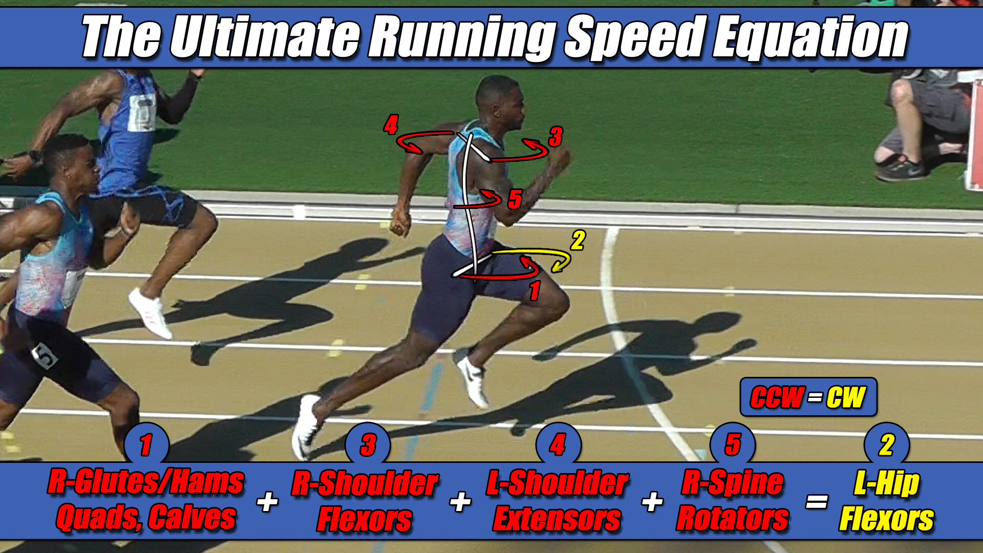 Left Hip Flexor Torque = CW. Everything Else CCW.