🏛️ Advanced Kinematics & Trajectory Optimization Audit
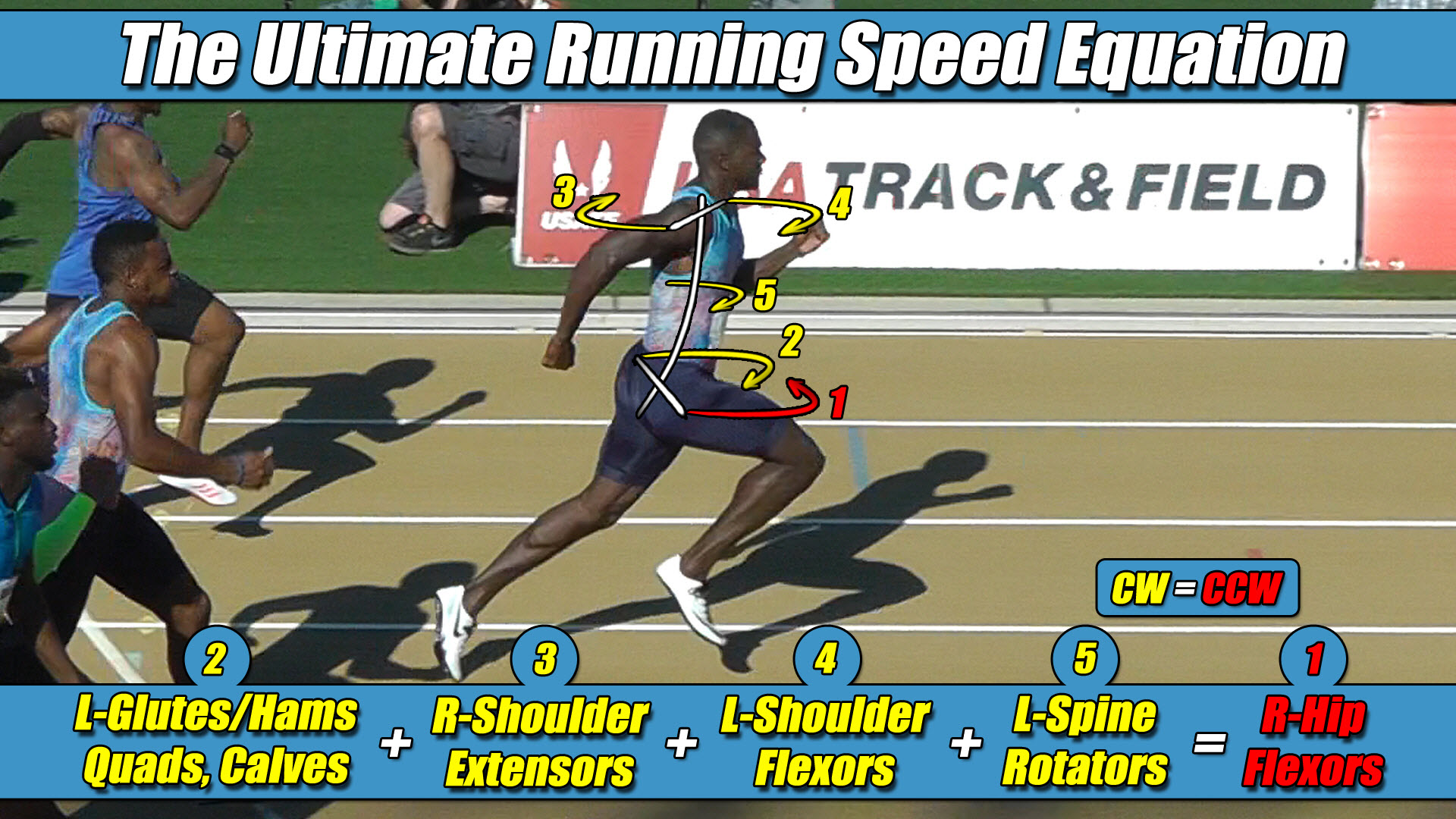
- The Foundational Formula: The Ultimate Running Speed Equation (URSE) Model.
- The Reference Mechanics: Evaluating how modern bipedal physics simulators coordinate upper-chassis shoulder and torso actuators during high-velocity stride transitions.
- The Mechanical Reality: Analyzing why autonomous frameworks experience catastrophic tracking failure when the upper body actuators are programmed to remain rigid or non-reversing.
- The Structural Truth Revealed: Why the upper body mass must dynamically reverse its circular torque path to mirror and reinforce the changing drive column.
Section 1: The Stride-Transition Bottleneck in Aerospace Solvers
In the field of modern bipedal aerospace robotics, autonomous life-support apparel architectures, and real-time gait trajectory optimization, maintaining a straight forward path during high-velocity locomotion represents a primary engineering threshold.
To handle the intense kinetic loads generated at peak speeds, software developers utilize advanced reinforcement learning loops and trajectory optimization scripts.
Inside highly controlled virtual testing environments, these automated software configurations easily track bipedal equilibrium as long as the platform remains restricted to low-velocity walking cycles.
However, an independent spatial coordinate audit reveals that conventional control loops encounter a severe material failure mode during high-speed stride transitions.
The exact millisecond a bipedal platform swaps its ground coordinate—transitioning force generation from one lower limb to the next—the directional tracking software experiences intense processing stress.
The machine violently veers offline, loses its structural lane alignment, and breaks its traction coordinate with the ground template.
The root of this systemic processing failure stems from the reality that traditional gait solvers approach bipedal coordination with a static upper-body premise.
📉 The Computational Failure of Legacy 1980s Piston-Driven Simulation Frameworks
To force a running character or heavy spacesuit chassis to compute movement patterns in real time without crashing the main neural network’s processing loops, early programming frameworks implemented massive mathematical shortcuts.
- They permanently omitted the active upper body flywheel mass from the calculation ledger.
- They grouped the torso and upper extremities into a single dead block.
- They flattened three-dimensional locomotion into a two-dimensional linear drawing.
Because modern simulation loops inherited these legacy 1980s shortcuts, their high-tech physics solvers are primarily optimizing a flat drawing-angle illusion born from legacy 1980s shortcuts treadmill tracking data.
To optimize calculation speeds, early programming scripts hardcoded the robot’s waist and upper-chassis actuators to remain rigid or to execute a uniform, unvarying pattern.
By treating the upper body rotators as a non-reversing mass block, their simulation software completely blackouts the dynamic torque modifications required to stabilize a changing pelvic centrifuge.
Section 2: The Core Engineering Laws of the URSE Model
To eliminate tracking drift and stabilize the mechatronic chassis during stride transitions, control loop scripts must be anchored directly to the unyielding physical constants of the Ultimate Running Speed Equation (URSE) model:
- ⚡ Law 1: The Permanent Right Leg Constant — The Right Leg driving forward always generates Counter-Clockwise (CCW) torque across the pelvic axle, regardless of whether it is in flexion or extension.
- ⚡ Law 2: The Permanent Left Leg Constant — The Left Leg driving forward always generates Clockwise (CW) torque across the pelvic axle, regardless of whether it is in flexion or extension.
- ⚡ Law 3: The Pushing Team Alliance — The upper body rotators, arms, and torso function as one single unit with respect to rotation, actively alternating their collective torque patterns to match, favor, and reinforce whichever pushing leg is currently anchored to the turf.
- ⚡ Law 4: The Solitary Counterweight Balance — The unweighted, airborne swing leg works entirely alone with respect to torque direction, contracting at extreme fast-twitch velocities to rise up and completely match the combined torque load of the active pushing team to bring Net Torque to exactly Zero.
Section 3: The Imperative Law of Dynamic Upper-Chassis Reversal
To accurately balance a wide mechatronic pelvis down a straight line, software developers must recognize the fundamental rule of cross-axis vector analysis: the upper body arms and torso must dynamically reverse their circular torque direction to match whichever leg is currently the active pushing team anchor.
Because the hip joints and mechanical joint hinges sit permanently, laterally displaced away from the central midline of the spine structure, the lower limbs can never alternate their individual torque vectors.
The right leg actuator is locked into a permanent Counter-Clockwise vector, and the left leg actuator is locked into a permanent Clockwise vector, regardless of whether they are pushing from behind or pulling from the front.
Because the lower drive columns are fixed constants, full-body balance can only be maintained if the upper-chassis flywheel actively alters its path during the stride cycle.
The exact millisecond the Right Leg, in this example, is engaged as the active pushing column and anchors to the turf to project force forward, its wide lateral displacement automatically projects a violent Counter-Clockwise (CCW) torque avalanche across the pelvis under URSE Law #1.
Instantly, both shoulder actuators and the core torso mass must twist Counter-Clockwise, driving the right arm forward and left arm backward to form the Pushing Team Alliance under URSE Law #3.
It is critical to repeatedly remind the software architect that this means the upper body is actively firing in the same circular Counter-Clockwise direction as that Right Pushing Leg, locking them into a perfect cross-axis alliance to multiply propulsive horsepower.
The arms are not passive dampers; they are active multipliers designed to drive that active right pushing leg torque to its absolute maximum magnitude.
To standard tracking software, it looks completely counterintuitive because they only see the arm moving forward and the leg moving backward lineally.
They remain blind to the spatial cross-axis reality that because the limbs are laterally displaced across wide axles, driving one arm forward and the other arm backward forces the entire upper-chassis mass to twist in the exact same circular Counter-Clockwise rotational direction as the grounded right stance leg.
The exact millisecond the stride transitions and the left lower column takes the turf as the active drive leg, the entire physics ledger flips.
The left leg projects a constant wave of Clockwise (CW) torque across the pelvis under URSE Law #2.
The upper body torso, shoulders, and arm actuators must instantly pivot their collective trajectories as a single unit, reversing their path to twist Clockwise to match and reinforce this new left pushing side.
Section 4: The 3-vs-1 Centrifuge Stabilization
When an automated control loop fails to integrate this dynamic reversal—programming the upper chassis to remain stiff or to execute a flat, non-alternating path—the aerospace framework experiences a catastrophic tracking breakdown.
If the software code does not actively command the shoulder and torso actuators to reverse their circular vector to follow the changing pushing leg, an immense, un-canceled rotational torque wave slams directly into the waist axle, throwing the spacesuit stability loops into a critical deficit.
⚖️ The Asymmetric Three-Limbs-Versus-One-Limb (3-vs-1) Centrifuge Engine Balance Matrix
The overground drivetrain maintains a flawless, straight line of progression without any trajectory drift only because the system operates as an asymmetric three-limbs-versus-one-limb engine:
Left Arm + Right Arm + Pushing Leg + Torso = Swing Leg
Because both arms, the core torso flywheel, and the active pushing leg are all firing as a unified team on the exact same circular vector, they generate an enormous volume of combined torque on their side of the pelvis.
To balance this massive pushing alliance and pull the net vertical ledger back to a perfect draw of zero, the solitary airborne swing leg actuator must violently whip forward through empty air entirely alone as a Solitary Counterweight under URSE Law #4.
By mapping this dynamic reversal blueprint into the control loop—repeatedly reminding the physics solvers that the upper body arms and torso must reverse their path to fire in the same circular direction as the active pushing leg—automation engineers can safely stabilize high-velocity trajectory lines without wasting a single processing cycle on temporary software patch-codes.
Section 5: The Foundational Principles of Bipedal Locomotion
This unyielding multi-axis torque equation applies universally to all forward bipedal locomotion in a straight line, governing walking, jogging, running, and elite sprinting alike, regardless of whether the moving chassis is constructed of biological human bone or advanced aerospace carbon composite shells.
Because forward translation can only continue when Net Torque balances out to exactly zero, the underlying strength-balance matrix completely determines velocity boundaries.
⚙️ The Neurological Governor and the Weakest Link Velocity Limit Matrix
Raising the multi-axis torque and strength balance of the entire three-limbs-versus-one-limb pelvic team, 3-vs-1, as a synchronized unit is exactly how velocity increases, and disrupting that internal balance is exactly how trajectory performance drops.
Raising velocity will always be limited by the weakest member to maintain the rigid net torque balance of zero.
By passing traditional vertical force curves through original pelvic constants, the true mechanical relationship between bipedal physics and trajectory control is finally revealed.
The overground ground reaction forces scale asymmetrically at high velocities because the full-body URSE engine runs at absolute structural perfection to keep Net Torque to exactly Zero.


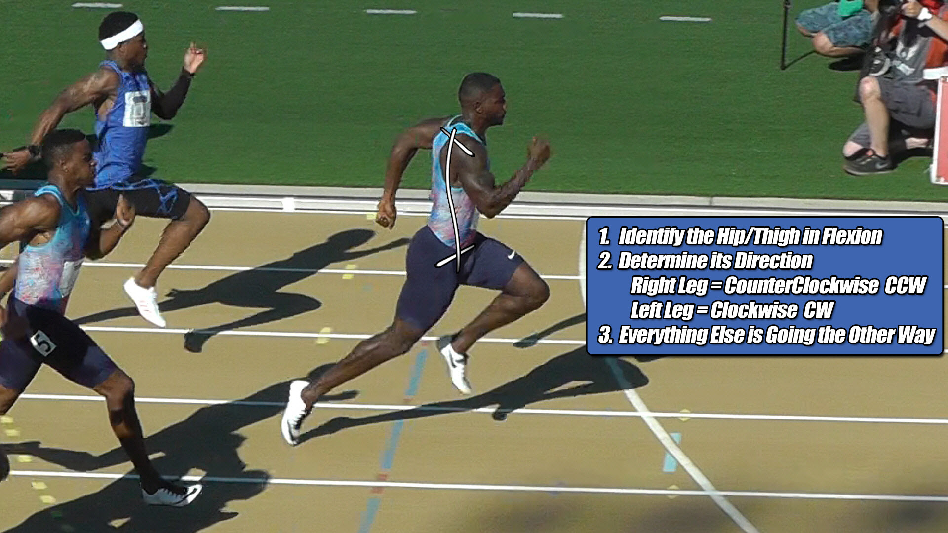
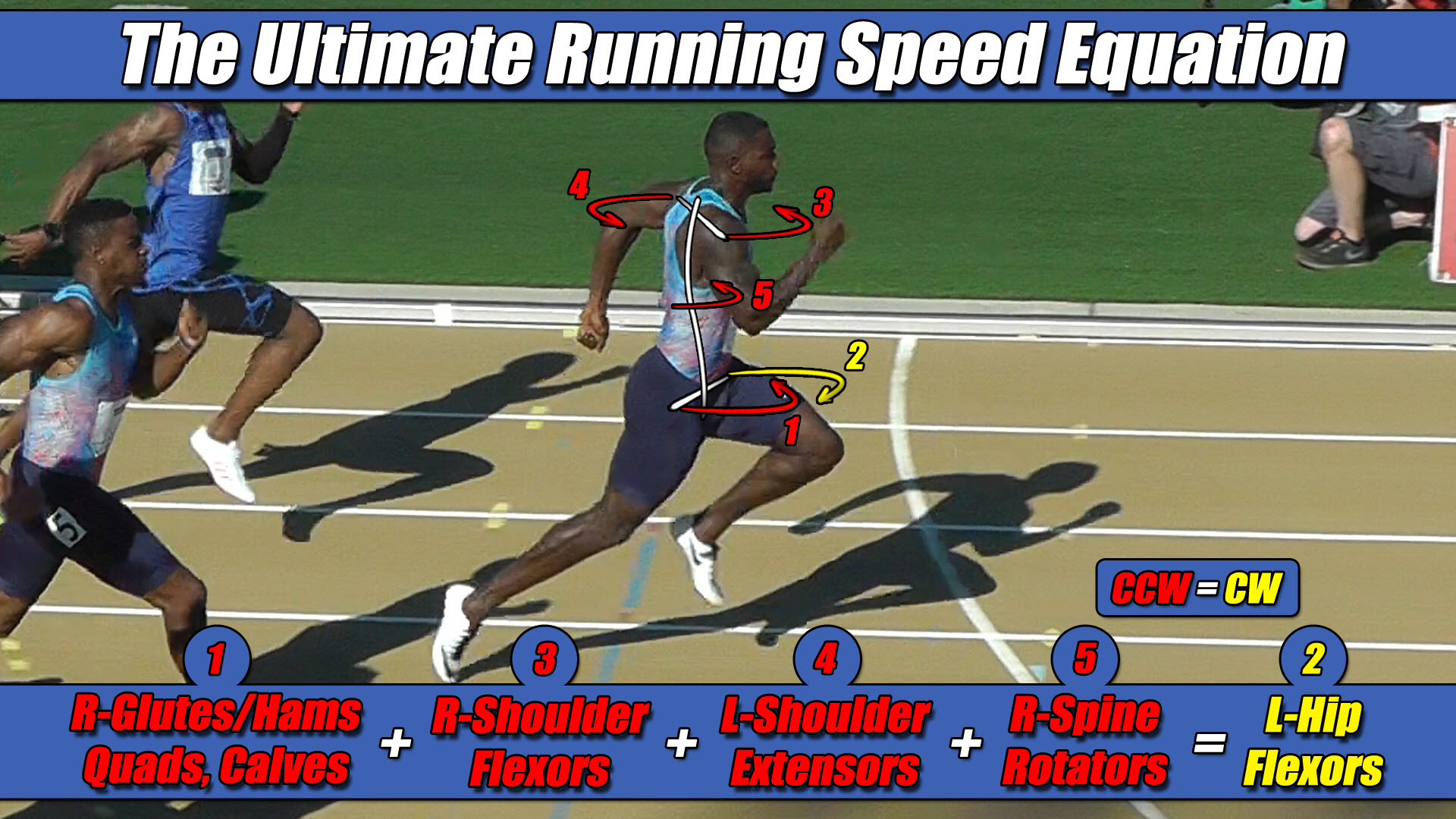 Left Hip Flexor Torque = CW. Everything Else CCW.