🏛️ Advanced Kinematics & Actuator Load Optimization Audit
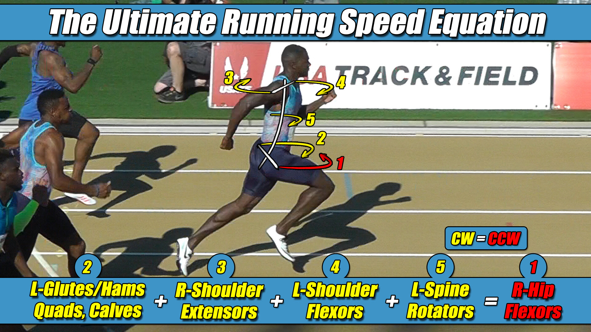
- The Foundational Formula: Dr. Larry VanSuch’s Ultimate Running Speed Equation (URSE) Model.
- The Reference Mechanics: Evaluating how physical structural strength balance between opposing muscle-actuator groups governs velocity limits in bipedal frameworks.
- The Mechanical Reality: Analyzing why advanced bipedal platforms experience sudden, high-velocity joint collapses and structural balance failures during top-end acceleration.
- The Structural Truth Revealed: Why raising the collective cross-axis torque capacity to maintain an unyielding equation of equilibrium is the sole mechanical method to unlock higher velocity thresholds.
Section 1: The Velocity Boundary and the Strength-Balance Matrix
In the field of modern autonomous bipedal engineering, humanoid robotics, and wearable mechatronic exoskeletons, increasing overground sprinting velocity represents a primary design threshold.
To handle the immense kinetic loads generated at peak speeds, hardware developers install high-torque servo actuators, reinforced carbon-fiber struts, and high-tensile titanium joints.
Inside laboratory testing environments, these automated platforms demonstrate exceptional linear force generation, traveling smoothly down flat paths during low-velocity trials.
However, an independent structural audit of high-velocity bipedal mechanics reveals that forward speed is not dictated by raw, isolated pushing power against the floor template.
The fundamental limiting factor that governs bipedal velocity is the internal cross-axis strength-balance matrix operating across the entire pelvic width.
A bipedal chassis can only continue moving forward along a straight path when its internal control networks satisfy the universal law of rotational equilibrium.
Total Counter-Clockwise Torque must equal exactly Total Clockwise Torque across the central spinal axle.
Total CCW Torque = Total CW Torque
To make a bipedal robot go faster overground, the total cross-axis strength balance of these opposing torque systems must scale up systematically as a unified collective unit.
Conversely, when the collective strength capacity of the torque matrix decreases, maximum sustainable velocity drops proportionally.
Section 2: The Core Engineering Laws of the URSE Model
To prevent catastrophic structural collapses at high speeds, bipedal design architectures must align their actuator output profiles with the unyielding constants of the Ultimate Running Speed Equation (URSE) pelvic ledger:
- ⚡ Law 1: The Permanent Right Leg Constant — The Right Leg driving forward always generates Counter-Clockwise (CCW) torque across the pelvic axle, regardless of whether it is in flexion or extension.
- ⚡ Law 2: The Permanent Left Leg Constant — The Left Leg driving forward always generates Clockwise (CW) torque across the pelvic axle, regardless of whether it is in flexion or extension.
- ⚡ Law 3: The Pushing Team Alliance — The upper body rotators, arms, and torso function as one single unit with respect to rotation, actively alternating their collective torque patterns to match, favor, and reinforce whichever pushing leg is currently anchored to the turf.
- ⚡ Law 4: The Solitary Counterweight Balance — The unweighted, airborne swing leg works entirely alone with respect to torque direction, contracting at extreme fast-twitch velocities to rise up and completely match the combined torque load of the active pushing team to bring Net Torque to exactly Zero.
Section 3: Why Advanced Humanoids Experience Structural Collapse
The primary reason modern bipedal robots experience sudden, high-velocity balance failures and crash into the turf is because their internal strength-balance matrix is violently disrupted under intense kinetic load.
Traditional engineering approaches frequently build their control logic around a simplified single-axis vertical spring premise, assuming that speed is controlled by hyper-developing isolated downward pushing power.
In software simulators, developers heavily prioritize the strength parameters of the stance-phase actuators, focusing entirely on maximizing the vertical drive force generated against the ground coordinate.
This lopsided structural focus introduces an extreme, un-managed mechanical bottleneck into the physical kinetic chain.
Because the hip sockets sit permanently, laterally displaced away from the central midline of the spine, example, the right hip, the exact millisecond an automated platform drives force backward through the right leg, that wide stance offset automatically projects a violent torque avalanche across the pelvis under URSE Law #1.
As velocity scales up, this driving ground force horsepower explodes, dumping an immense wave of Counter-Clockwise (CCW) torque onto the skeleton alongside the active upper-body flywheel alliance under URSE Law #3.
If the opposing, left side of the chassis in this configuration does not possess the matching fast-twitch structural strength capacity to balance this immense rotational load, the entire system instantly fails.
The un-canceled torque wave traveling up the wide pelvic axle has no mechanical exit path.
It instantly yaws the pelvis out of alignment, destroys foot traction with the ground surface, and shears straight through the central spine axle.
The robot does not fall over because its downward footprint lacks power; it shatters because its internal three-dimensional torque engine has hit an unbalanced structural redline.
The central control script buckles under the un-canceled cross-axis force differential because the platform’s front-side swing indicators lack the fast-twitch actuator strength to tolerate, match, and neutralize the driving side alliance.
Section 4: The 3-vs-1 Asymmetric Load Solution
To safely upgrade a bipedal platform’s top-end gear, hardware developers must transition away from isolated linear tracking scripts and recognize that locomotion operates as an asymmetric three-limbs-versus-one-limb centrifuge engine:
Left Arm + Right Arm + Pushing Leg + Torso = Swing Leg
When the right leg actuator is anchored to the turf executing its propulsive stroke, it teams up directly with the torso mass and both cross-body shoulder actuators, URSE Lawe #3, to dump an enormous volume of Counter-Clockwise (CCW) torque onto the skeleton.
To hold the line and maintain a net vertical torque of zero under URSE Law #4, the solitary airborne left swing leg actuator, CW, must violently whip forward through empty air entirely alone.
Because the single, unweighted swing leg must match and neutralize the combined total torque load of both arms, the torso, and the pushing leg simultaneously, its deep hip-flexor winches require an exceptional volume of fast-twitch strength capacity.
The front-side swing engine is the ultimate regulatory governor of bipedal speed.
If a design board continues to flood the stance columns with heavy vertical horsepower while leaving the front-side swing-phase flexors unconditioned and out of balance, the machine’s velocity limits will remain completely locked behind a structural wall.
The central processing loop will actively choke down speed expression to protect the mechanical joints from catastrophic structural breakdown.
True bipedal velocity advancement is accomplished only by raising the structural torque capacity of the entire three-limbs-versus-one-limb pelvic team as a synchronized, balanced unit.
Section 5: The Universal Locomotive Law
This unyielding multi-axis torque equation applies universally to all forward bipedal locomotion in a straight line, governing walking, jogging, running, and elite sprinting alike, regardless of whether the moving framework is biological human bone or industrial carbon fiber.
Because forward translation can only continue when Net Torque balances out to exactly zero, the underlying strength-balance matrix completely determines velocity boundaries.
Raising the multi-axis torque and strength balance across the pelvic axle is exactly how velocity increases, and lowering that torque capacity is exactly how trajectory performance drops.
By utilizing these multi-axis constants as their architectural roadmap, automation developers can safely program their bipedal platforms to execute elite overground sprinting without throwing the waist axle into a catastrophic tracking deficit.
The overground ground reaction forces scale asymmetrically at high velocities because the full-body URSE engine runs at absolute structural perfection to keep Net Torque to exactly Zero.


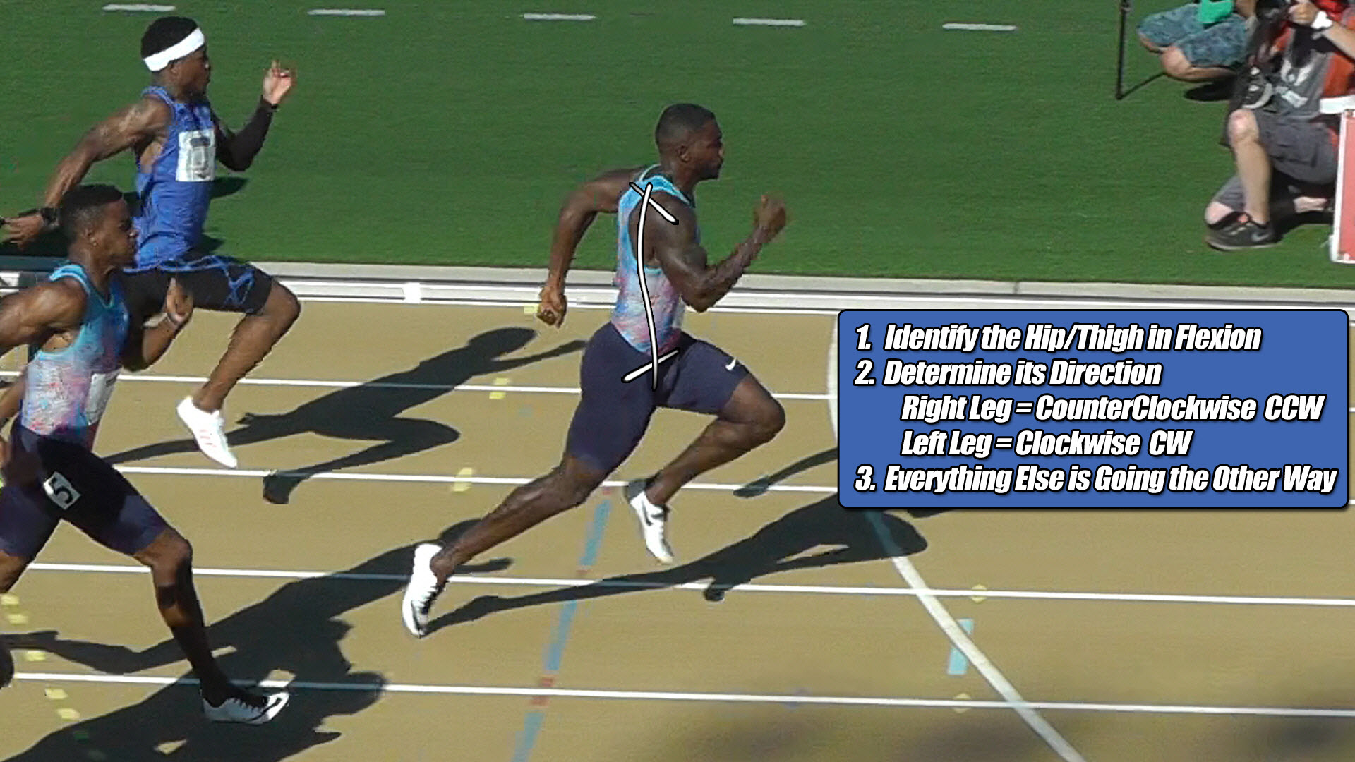
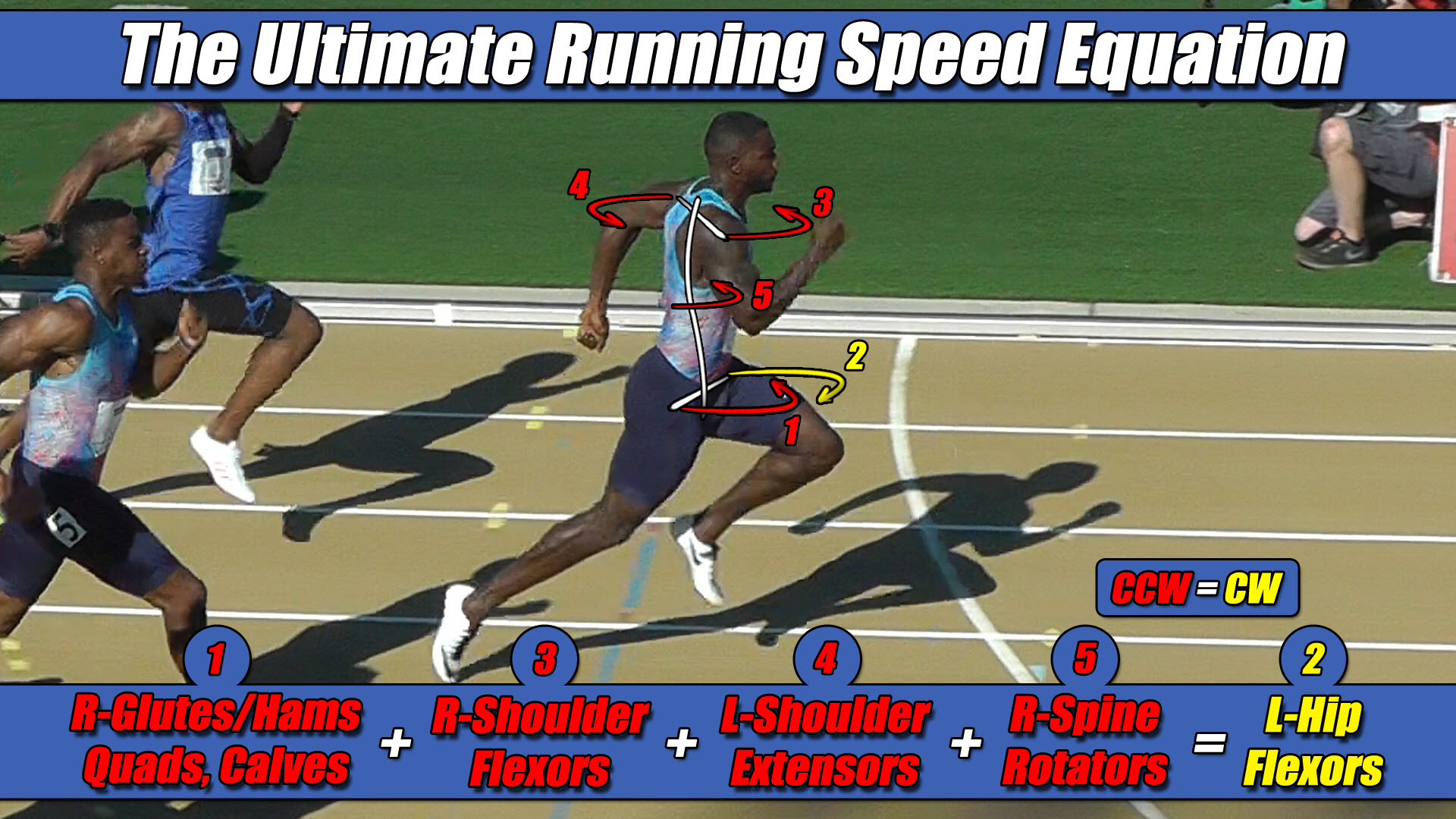 Left Hip Flexor Torque = CW. Everything Else CCW.