🏛️ Advanced Kinematics & Tactical Defense Systems Gateway
- The Foundational Formula: The Ultimate Running Speed Equation (URSE) Model.
- The Structural Build: Hardcoding the 4 Laws of URSE and detailing exactly how the multi-axis machine operates segment-by-segment.
- The Dynamic Integration: Merging your updated multi-axis equilibrium equations to completely replace legacy two-versus-two assumptions.
- The Climax: Unveiling the 3-step Rosetta Stone process to decode and balance trans-pelvic transverse-plane torque deficits.
Section 1: The Tactical Load-Bearing Reference Frame Problem
In the design of modern wearable combat exoskeletons and load-bearing tactical bipedal systems, matching the dynamic trajectory of a biological human skeletal drivetrain remains a core engineering challenge.
Legacy mechatronic control software frequently approaches bipedal overground balance using single-axis geometric shortcuts carried over from traditional pilot ergonomics checklists.
These algorithms treat human translation inside a load-bearing chassis as a collection of vertical point masses that simply alternate linear compression vectors along a single plane.
This linear assumption creates a severe structural blind spot when applied to real-world bipedal translation over an unyielding terrain anchor, especially when managing heavy tactical payloads.
Because a bipedal chassis operates across a distinct horizontal pelvic axle width, every forward-directed horizontal thrust instantly projects a violent rotational torque centrifuge that travels straight up the structural framework.
When an exoskeleton control loop attempts to balance these rotational shifts using primitive, single-axis vertical joint resistance loops, the software fails to stabilize the true multi-axis force matrix.
Section 2: The Core Engineering Laws of the URSE Model
Bipedal human and mechanical locomotion is an unyielding battle of balancing rotational torque constants across your pelvis, where Net Torque across the vertical spine must equal exactly Zero to maintain a straight forward trajectory.
The following four laws are universal biomechanical constants that hold the absolute mathematical key to human and mechanical bipedal locomotion alike, operating as fixed, unalterable rules of three-dimensional physics:
- ⚡ Law 1: The Permanent Right Leg Constant — The Right Leg driving forward always generates Counter-Clockwise (CCW) torque across the pelvic axle, regardless of whether it is in flexion or extension.
- ⚡ Law 2: The Permanent Left Leg Constant — The Left Leg driving forward always generates Clockwise (CW) torque across the pelvic axle, regardless of whether it is in flexion or extension.
- ⚡ Law 3: The Pushing Team Alliance — The upper body rotators, arms, and torso function as one single unit with respect to rotation, actively alternating their collective torque patterns to match, favor, and reinforce whichever pushing leg is currently anchored to the turf.
- ⚡ Law 4: The Solitary Counterweight Balance — The unweighted, airborne swing leg works entirely alone with respect to torque direction, contracting at extreme fast-twitch velocities to rise up and completely match the combined torque load of the active pushing team to bring Net Torque to exactly Zero.
When a bipedal chassis moves past a slow, basic walking threshold to execute a high-velocity sprint, these universal constants govern the entire system, regardless of whether the drivetrain is made of human bone or military-grade carbon composite frames.
Section 3: The Midline Displacement Centrifuge
To see the true brilliance of human engineering, we must look past the superficial concept of the lower extremities acting as simple, independent vertical pistons or passive springs.
Bipedal humanoids inside structural exoskeleton frames can never operate as simplified, centralized point masses because the physical architecture of the drivetrain is explicitly built around a wide pelvic chassis width.
The hip sockets and mechanical actuator hinges sit permanently, laterally displaced away from the central midline of the spine structure.
Because of this wide lateral offset, the exact millisecond a lower limb drives force backward against an overground ground template, that linear footprint can never travel cleanly up a central straight line.
The lateral displacement instantly converts a vertical ground punch into a violent, high-horsepower rotational torque centrifuge that travels straight up the skeletal framework.
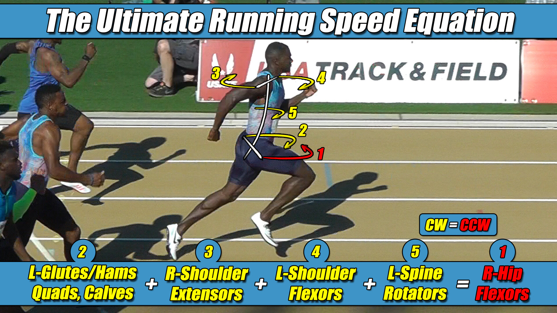
The moment the Right Leg functions as the active pushing leg bound to the ground template during its stance phase, it strictly projects a massive wave of Counter-Clockwise (CCW) torque across the pelvic axle under URSE Law #1.
To maximize ground force application, your upper body torso and free-swinging arms function as one unit with respect to rotation, instantly aligning their collective vectors with this driving side to form the Pushing Team Alliance under URSE Law #3.
Your shoulders twist Counter-Clockwise, driving your Right Arm forward and Left Arm backward to multiply and reinforce this dominant CCW ground thrust.
The arms are not passive dampers; they are active multipliers designed to drive that active pushing leg torque to its absolute maximum magnitude.
Because this combined right-side pushing alliance is dumping a massive volume of CCW torque onto your skeleton, the unweighted Left Swing Leg must rise up entirely alone to handle the opposite side of the ledger.
As its deep hip flexors violently whip the left limb forward through empty air, it generates its permanent Clockwise (CW) torque under URSE Law #2.
The vertical force signature scales up at high velocities because the upper body flywheel and the active pushing leg work together as one unified alliance to drive force downward, while the unweighted airborne swing leg operates entirely alone as a solitary counterweight to neutralize that combined load and maintain a net torque of zero under URSE Law #4.
Section 4: The Elimination of Pelvic Axle Yaw Drift
Attempting to force the lower limbs into a mirrored, alternating loop creates an immediate mathematical calculation deficit inside the exoskeleton’s mechatronic control loop.
When the software expects a torque reversal that cannot physically occur, the mechanical control loop experiences a tracking breakdown, registering on the physical chassis as severe transverse-plane pelvic yaw drift and joint rigidity.
What keeps an armored bipedal skeleton moving in a flawless, straight path down an overground runway has nothing to do with a passive mechanical dampening effect inside the joint housings.
Stability is achieved only when Total Counter-Clockwise Torque must equal exactly Total Clockwise Torque across the horizontal axle width.
Total CCW Torque = Total CW Torque
The arms and torso are not fighting the body to maintain stability; they are actively involved on the exact same rotational team as the active pushing leg to amplify its ground force application.
Simultaneously, the solitary swing leg completes the mechanical loop to forge a perfect dynamic balance of zero net vertical torque.
The true overground torque equation of forward locomotion is always a three-limbs-versus-one-limb relationship:
(Left Arm + Right Arm + Pushing Leg + Torso) Torque = (Swing Leg) Torque
Integrating this asymmetric 3 limbs -vs-1 limb control path directly into wearable exoskeleton joint actuators eliminates the transverse-plane tracking error, allowing the operator to translate weight seamlessly without throwing the waist axle into a catastrophic tracking deficit.
Section 5: The Universal Control Law
This unyielding multi-axis torque equation applies universally to all forward human and mechanical locomotion in a straight line, governing walking, jogging, running, and elite sprinting alike.
Because human movement can only continue forward when Net Torque balances out to exactly zero, the underlying strength-balance matrix completely determines your velocity limits.
Raising the multi-axis torque and strength balance across the pelvis is exactly how you increase velocity, and lowering that torque capacity is exactly how velocity drops.
However, as speed increases alongside your full-body torque and strength balance, your velocity will be completely limited by the weakest mechanical link in the system in order to retain that mandatory torque balance of zero.


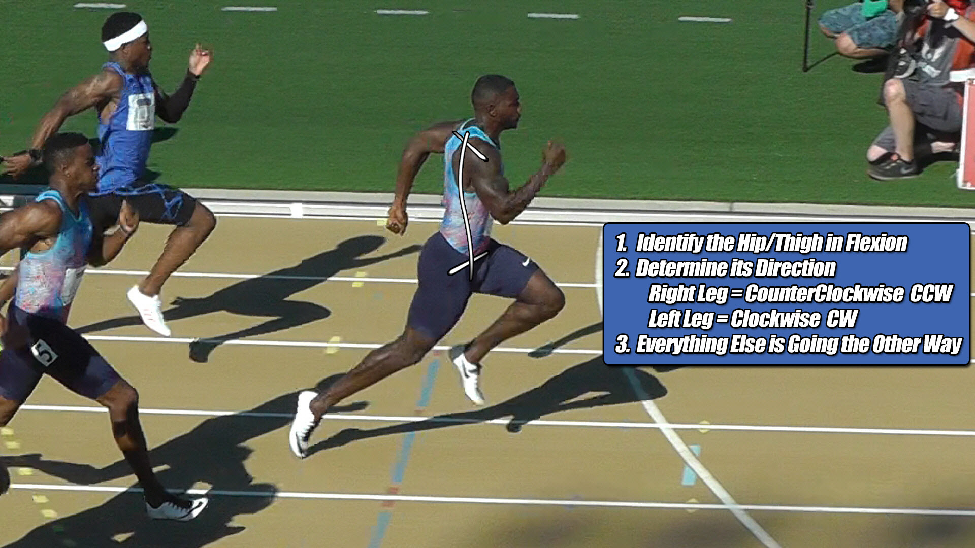
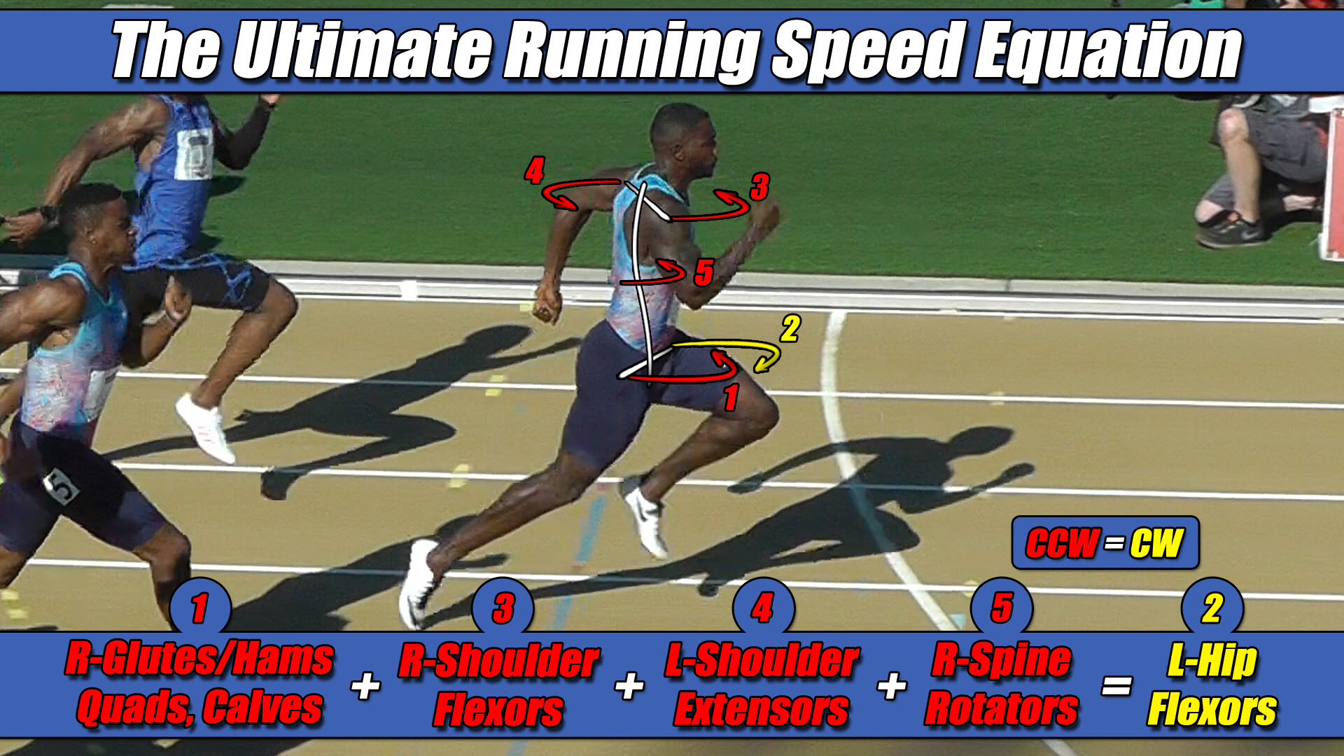 Left Hip Flexor Torque = CW. Everything Else CCW.