🏛️ Advanced Kinematics & Trajectory Optimization Audit
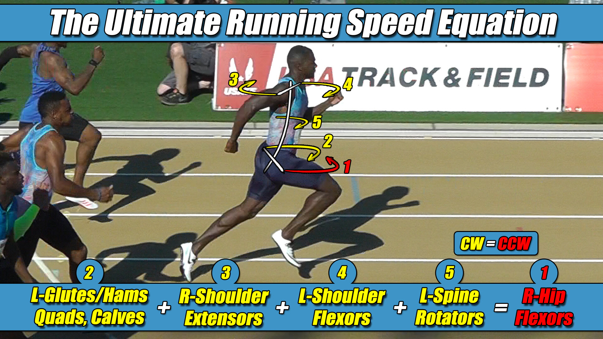
- The Foundational Formula: The Ultimate Running Speed Equation (URSE) Model.
- The Reference Mechanics: Evaluating how modern microprocessor-controlled lower-limb prosthetics manage horizontal twisting forces during high-velocity forward translation.
- The Mechanical Reality: Analyzing why autonomous frameworks experience un-managed trajectory drift and tracking loss when accelerating down a straightaway lane.
- The Structural Truth Revealed: Why integrating an asymmetric three-limbs-versus-one-limb (3-vs-1) torque equation provides the definitive physical parameters to stabilize the pelvic axle.
Section 1: The Trajectory Drift Limitation in Prosthetic Control Loops
In the field of advanced bipedal prosthetics, autonomous navigation scripts, and high-fidelity locomotion simulations, maintaining a straight forward trajectory at peak velocity represents a primary engineering objective.
To optimize overground stability, automated control loop developers utilize high-speed processing clusters to continuously calculate ground reaction forces and joint torque variables.
Inside highly structured prosthetic microprocessors, simulation scripts successfully balance bipedal frameworks during low-velocity walking cycles by tracking localized vertical force parameters.
However, as a bipedal humanoid platform transitions from a casual walk into a high-velocity sprint, automated data logs frequently document a severe trajectory drift bottleneck.
The exact millisecond the bipedal chassis reaches peak velocity thresholds, the directional control loops encounter an intense rotational force differential.
The machine yaws out of alignment, breaks residual limb socket traction with the ground template, and veers violently offline away from its intended path of progression.
The underlying limitation behind this directional tracking failure stems from the reality that traditional gait solvers approach bipedal balance using a single-axis vertical premise.
To optimize calculation speeds, early simulation codes treated the entire moving skeleton as a centralized, non-rotating point mass.
This simplified configuration permanently omitted the cross-axis interactions running across a wide pelvic chassis width, leaving modern developers without a comprehensive horizontal ledger to stabilize high-velocity torque loads.
Section 2: The Core Engineering Laws of the URSE Model
To prevent trajectory drift and eliminate rotational tracking failure, prosthetic control loops must design their tracking scripts to operate within the unyielding multi-axis engineering constants of the Ultimate Running Speed Equation (URSE) pelvic ledger:
- Law 1: The Permanent Right Leg Constant — The Right Leg driving forward always generates Counter-Clockwise (CCW) torque across the pelvic axle, regardless of whether it is in flexion or extension.
- Law 3: The Permanent Left Leg Constant — The Left Leg driving forward always generates Clockwise (CW) torque across the pelvic axle, regardless of whether it is in flexion or extension.
- Law 3: The Pushing Team Alliance — The upper body rotators, arms, and torso function as one single unit with respect to rotation, actively alternating their collective torque patterns to match, favor, and reinforce whichever pushing leg is currently anchored to the turf.
- Law 4: The Solitary Counterweight Balance — The unweighted, airborne swing leg works entirely alone with respect to torque direction, contracting at extreme fast-twitch velocities to rise up and completely match the combined torque load of the active pushing team to bring Net Torque to exactly Zero.
These four universal laws define the exact physical parameters that an autonomous software network must satisfy to maintain a net vertical torque of zero across the central spine axle.
Section 3: The Three-Limbs-Versus-One-Limb Centrifuge Engine
A bipedal structure utilizing an artificial limb can never achieve high-velocity linear stability through an even, two-versus-two mirrored loop cancellation model, because real overground physics are inherently asymmetric.
Because the hip joints and residual limb socket interfaces sit permanently, laterally displaced away from the central midline of the spine, any linear ground force traveling up a stance column instantly converts into a violent rotational centrifuge.
The exact millisecond a right prosthetic actuator fires backward to drive propulsion forward, its wide stance offset automatically unleashes a massive wave of Counter-Clockwise (CCW) torque across the pelvic axle width under URSE Law #1.
To maximize ground force expression, the upper extremities, shoulder assemblies, and torso mass must actively twist as a unified flywheel in a matching Counter-Clockwise direction to form the Pushing Team Alliance under URSE Law #3.
The arms and upper chassis do not function as passive shock dampers; they operate on the exact same rotational team as the active driving leg to amplify its ground force horsepower.
Because this combined driving alliance dumps an immense volume of CCW torque onto the skeleton, the unweighted, airborne swing leg must rise up entirely alone to handle the opposite side of the ledger.
As its deep hip accelerators violently whip the limb forward through empty air, its movement projects a permanent Clockwise (CW) torque vector under URSE Law #2.
The airborne swing leg functions as a solitary fast-twitch counterweight, single-handedly balancing the massive torque load of both arms, the torso, and the pushing leg combined to bring Net Torque to exactly Zero under URSE Law #4.
The overground torque equation of forward locomotion is always a three-limbs-versus-one-limb relationship:
Left Arm + Right Arm + Pushing Leg + Torso = Swing Leg
Section 4: The Strategic Advisory Solution
To fix high-velocity trajectory drift and alleviate severe transverse-plane socket shear, mechatronic developers do not need to alter their hardware configurations or expand their raw computational processing power.
The technical solution requires software programming teams to update their underlying trajectory code bases to align directly with these unyielding asymmetric constants.
By applying this three-limbs-versus-one-limb physical map, software architects can configure their neural network reward weights to recognize that the vertical force spike registered on a ground plate is a whole-body stabilization event rather than an independent linear compression vector.
The vertical force signature scales up at high velocities because the upper body arms, torso and the active pushing leg work together as one unified alliance to drive force downward, while the unweighted airborne swing leg operates entirely alone as a solitary counterweight to neutralize that combined load and maintain a net torque of zero.
By utilizing these multi-axis constants as their architectural roadmap, automation developers can safely program their microprocessor-controlled lower-limb prosthetics to execute elite overground sprinting without throwing the waist axle into a catastrophic tracking deficit.
Section 5: The Universal Locomotive Law
This unyielding multi-axis torque equation applies universally to all forward bipedal locomotion in a straight line, governing walking, jogging, running, and elite sprinting alike, regardless of whether the moving chassis is constructed of biological human bone or advanced microprocessor-controlled carbon fiber.
Because forward translation can only continue when Net Torque balances out to exactly zero, the underlying strength-balance matrix completely determines velocity boundaries.
Raising the multi-axis torque and strength balance across the pelvic axle is exactly how velocity increases, and lowering that torque capacity is exactly how trajectory performance drops.
By passing traditional vertical force curves through original pelvic constants, the true mechanical relationship between bipedal physics and trajectory control is finally revealed.
The ground reaction forces scale asymmetrically at high velocities because the full-body URSE engine runs at absolute structural perfection to keep Net Torque to exactly Zero.


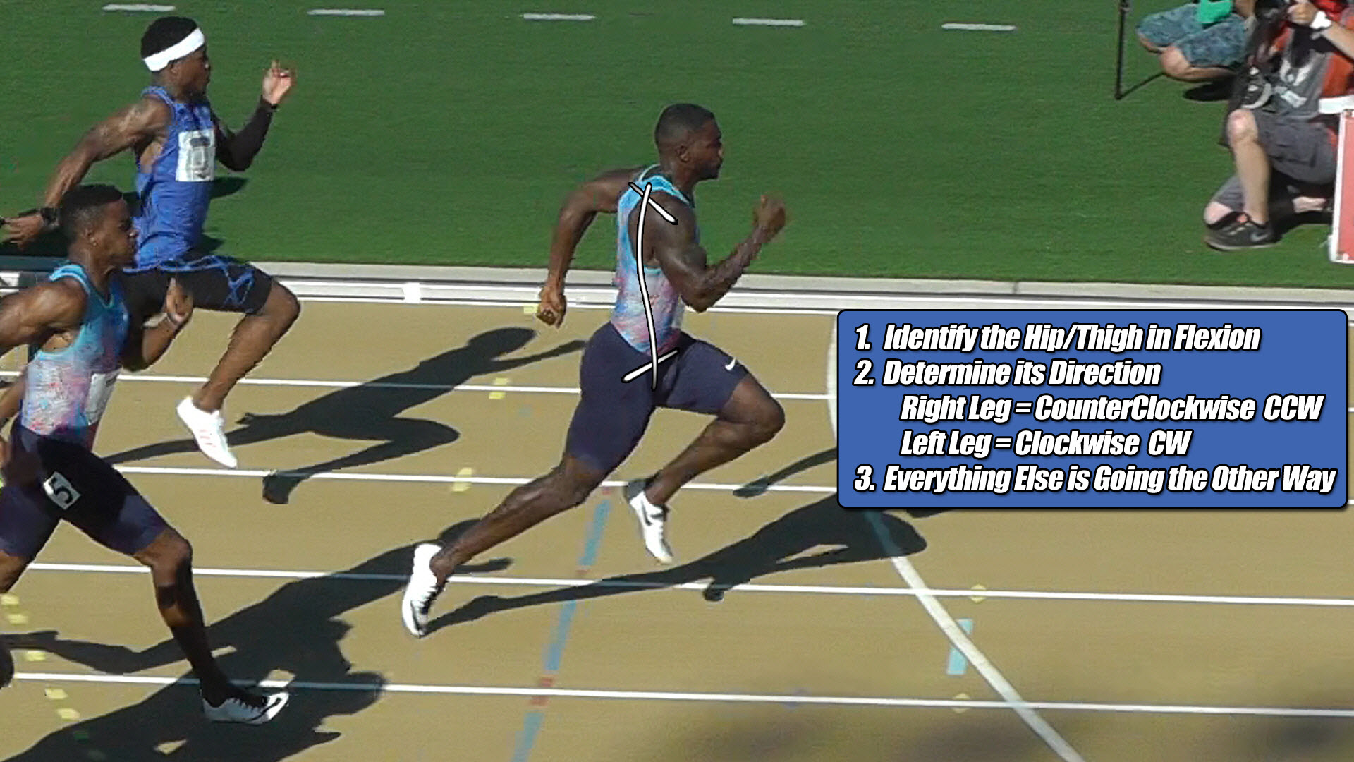
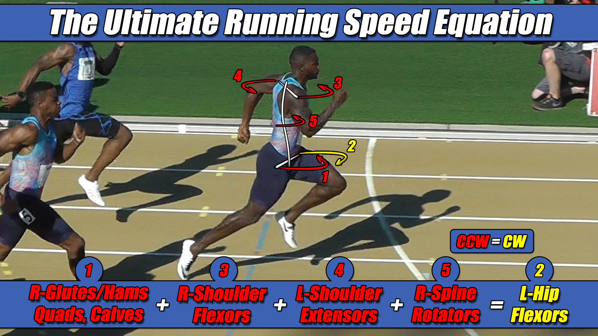 Left Hip Flexor Torque = CW. Everything Else CCW.