Advanced Kinematics & Biomechatronic Prosthetics Gateway
- The Foundational Formula: The Ultimate Running Speed Equation (URSE) Model.
- The Structural Build: Hardcoding the 4 Laws of URSE and detailing exactly how the multi-axis machine operates segment-by-segment.
- The Dynamic Integration: Merging your updated multi-axis equilibrium equations to completely replace legacy symmetrical assumptions.
- The Climax: Unveiling the 3-vs-1 Rosetta Stone process to decode and balance trans-pelvic transverse-plane torque deficits.
Section 1: The Mechatronic Mirror: Machines Model Humans
In the development of advanced prosthetics, artificial limbs, and wearable autonomous systems, the biological human skeletal drivetrain serves as the ultimate engineering blueprint for efficiency and balance.
Every complex bipedal mechanism designed across modern biomechatronic laboratories is a deliberate, mechanical attempt to replicate the organic perfection of human movement.
From advanced microprocessor-controlled knee units engineered to copy biological joint transitions, to carbon-fiber foot plates designed to mirror elastic energy storage, adaptive technology consistently climbs toward the human experience.
A fundamental rule of automated development dictates that machines do not model prosthetics; rather, prosthetic design models humans by attempting to replicate biological sensory input and motor output.
When advanced mechatronic labs construct next-generation hardware platforms, they are seeking to reproduce the exact multi-axis equilibrium that allows a bipedal framework to translate force smoothly through space over solid ground.
Because technology always patterns its blueprints off some aspect of human biology, the definitive keys that govern human velocity hold the absolute structural source code to the future of bipedal prosthetics.
Section 2: The Core Engineering Laws of the URSE Model
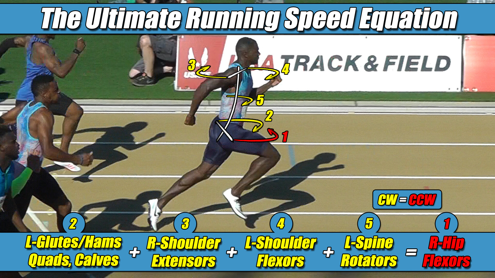
Human locomotion is an unyielding battle of balancing rotational torque constants across your pelvis, where Net Torque across the vertical spine must equal exactly Zero to maintain a straight forward trajectory down a real-world pathway.
The following four laws are universal biomechanical constants that hold the absolute mathematical key to human gait and prosthetic locomotion alike, operating as fixed, unalterable rules of three-dimensional physics:
- Law 1: The Permanent Right Leg Constant — The Right Leg driving forward always generates Counter-Clockwise (CCW) torque across the pelvic axle, regardless of whether it is in flexion or extension.
- Law 2: The Permanent Left Leg Constant — The Left Leg driving forward always generates Clockwise (CW) torque across the pelvic axle, regardless of whether it is in flexion or extension.
- Law 3: The Pushing Team Alliance — The upper body rotators, arms, and torso function as one single unit with respect to rotation, actively alternating their collective torque patterns to match, favor, and reinforce whichever pushing leg is currently anchored to the turf.
- Law 4: The Solitary Counterweight Balance — The unweighted, airborne swing leg works entirely alone with respect to torque direction, contracting at extreme fast-twitch velocities to rise up and completely match the combined torque load of the active pushing team to bring Net Torque to exactly Zero.
When a bipedal chassis moves past a slow, basic walking threshold to execute a high-velocity sprint, these universal constants govern the entire system, regardless of whether the drivetrain is made of human bone or a carbon-fiber prosthetic assembly.
Section 3: The Dynamic Torque Engine: How the Prosthetic Operates
To see the true brilliance of human engineering, we must look past the superficial concept of lower-limb prosthetics acting as simple, independent vertical pistons or passive vertical springs.
Bipedal humanoids utilizing adaptive limbs can never operate as simplified, centralized point masses because the physical architecture of the drivetrain is explicitly built around a wide pelvic chassis width.
The hip sockets sit permanently, laterally displaced away from the central midline of the spine structure.
Because of this wide lateral offset, the exact millisecond a lower limb drives force backward against an overground ground template, that linear footprint can never travel cleanly up a central straight line.
The lateral displacement instantly converts a vertical ground punch into a violent, high-horsepower rotational torque centrifuge that travels straight up the skeletal framework.
The Right Leg Driving Constants
Consider the baseline setup of locomotion where the Right Leg is currently the active pushing leg bound to the ground template during its stance phase.
This driving Right Leg strictly projects a massive wave of Counter-Clockwise (CCW) torque across your pelvic axle under URSE Law #1.
To maximize ground force application, your upper body torso and free-swinging arms function as one unit with respect to rotation, instantly aligning their collective vectors with this driving side to form the Pushing Team Alliance under URSE Law #3.
Your shoulders twist Counter-Clockwise, driving your Right Arm forward and Left Arm backward to multiply and reinforce this dominant CCW ground thrust.
The arms are not passive dampers; they are active multipliers designed to drive that active pushing leg torque to its absolute maximum magnitude.
Because this combined right-side pushing alliance is dumping a massive volume of CCW torque onto your skeleton, the unweighted Left Swing Leg must rise up entirely alone to handle the opposite side of the ledger.
As its deep hip flexors violently whip the left limb forward through empty air, it generates its permanent Clockwise (CW) torque under URSE Law #2.
This action serves as the solitary counterweight to neutralize the entire pushing team alliance and bring Net Torque to exactly Zero under URSE Law #4.
The Left Leg Stride Transition
The split-second the system transitions to the next stride down the track, only the upper body torso and arms alternate their torque patterns to once again match the active pushing leg under URSE Law #3.
This time, however, it’s the Left Leg which is bound to the turf as the active pushing leg, which remains a constant Clockwise (CW) torque generator across the pelvic axle under URSE Law #2.
The legs themselves have not changed their torque direction, as any direction switch is physically impossible while both columns are projecting forward and displaced from the midline.
Instead, the upper body torso and arms dynamically pivot their collective patterns as one unit to align with this new pushing side.
The shoulders twist Clockwise, driving the Left Arm forward and Right Arm backward to match and reinforce the dominant CW ground thrust.
To balance this massive left-side CW pushing alliance, the Right Swing Leg must now violently rise up through thin air entirely alone, contracting at extreme velocities to project its permanent Counter-Clockwise (CCW) torque under URSE Law #1 to keep the spinal axle perfectly balanced to a net torque of zero under URSE Law #4.
Section 4: The Elimination of Transverse Socket Shear
The elimination of horizontal side-to-side body deviations and socket shear stress recorded across advanced engineering laboratories has nothing to do with a passive, mechanical dampening effect inside the prosthetic socket.
What keeps the adaptive skeleton moving in a flawless, straight path down a real-world pathway is one thing and one thing only: Total Counter-Clockwise Torque must equal exactly Total Clockwise Torque.
Total CCW Torque = Total CW Torque
The arms and torso are not fighting the body to maintain stability; they are actively involved on the exact same rotational team as the active pushing leg to amplify its ground force application.
Simultaneously, the solitary swing leg completes the mechanical loop to forge a perfect dynamic balance of zero net vertical torque.
This exact mathematical balance is what prevents any lateral deviation down the straightaway.
The upper extremities are not passive shock dampers; they are active, necessary components in the overall multi-axis equilibrium of bipedal locomotion.
The critical difference between this structural reality and traditional prosthetic interpretations is that legacy mechatronic software models view this balance as the entire upper body simply canceling out the entire lower body’s rotation.
That institutional assumption is completely false.
The true overground torque equation of forward locomotion is actually:
Left Arm + Right Arm + Pushing Leg + Torso = Swing Leg
This represents a major mechanical difference that completely alters the biomechatronic paradigm, showing that the arms are certainly not passive dampers.
They are part of a three-limbs-versus-one-limb, 3-vs-1, torque pattern, not a two-versus-two, 2-vs-2 mirrored loop.
Section 5: The Universal Locomotive Law
This unyielding multi-axis torque equation applies universally to all forward human and prosthetic locomotion in a straight line, governing walking, jogging, running, and elite sprinting alike.
Because bipedal movement can only continue forward when Net Torque balances out to exactly zero, the underlying strength-balance matrix completely determines your velocity limits.
Raising the multi-axis torque and strength balance across the pelvis is exactly how you increase velocity, and lowering that torque capacity is exactly how velocity drops.
However, as speed increases alongside your full-body torque and strength balance, your velocity will be completely limited by the weakest mechanical link in the system in order to retain that mandatory torque balance of zero.


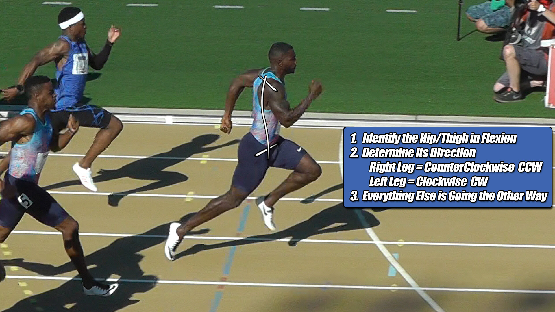
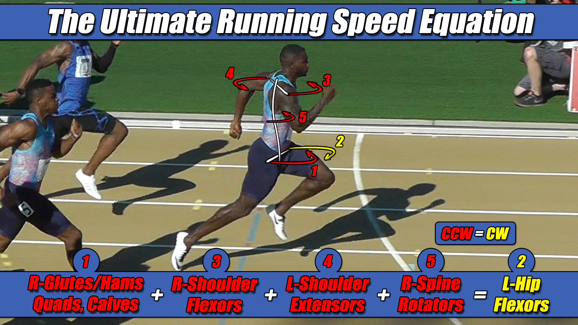 Left Hip Flexor Torque = CW. Everything Else CCW.