
Section 1: The Flat Surface Trapping of Zero Moment Point Logic
The Stabilization Standard of Modern Humanoid Platforms
In the domains of autonomous humanoid bipedal robotics, biomechanical sports analytics, and high-fidelity video game engine trajectory generation, maintaining absolute stabilization across asymmetric overground strides represents a critical engineering frontier.
To manage balancing vectors, software architects heavily rely on the Zero Moment Point (ZMP) framework.
The ZMP model operates on a single, core assumption: as long as the net tipping moments of all acting inertial and gravitational forces align cleanly within the physical boundaries of the biped’s foot contact patch on the floor, the machine will maintain its upright equilibrium without falling.
The Historical Origin of the 1970s Laboratory Patch
This methodology traces its roots back to basic laboratory papers published between 1969 and 1972.
At that time, ZMP was never engineered to be a definitive, high-velocity locomotive solution; it was simply a rudimentary diagnostic math patch required to safely turn an early hydraulic biped on and get it to lift a foot without instantly collapsing in a laboratory room.
While this primitive, flat-surface balancing logic functions cleanly across low-speed walking patterns inside controlled settings, it exposes a massive operational breakdown the exact millisecond a machine or digital asset attempts an intense high-velocity maneuver.
The High-Speed Rotational Force Fracture
The ZMP algorithm is fundamentally non-scalable because it treats balancing as an isolated, reactive pressure-balancing event taking place exclusively at the ground-contact floor plane.
It assumes the body can be stabilized by constantly modulating foot placement forces against a flat floor, completely ignoring the fact that high-speed bipedal locomotion is driven by violent, complex rotational forces originating high above the ground.
When an advanced biped executes an explosive lateral acceleration, a sudden bracing stop, or an un-anchored mid-air orientation change, the ZMP equations fracture.
The Low-Speed Box of Legacy Software Patches
Because the model completely lacks three-dimensional pelvic rotation mass parameters, the internal computation engine cannot process the rapid torque changes moving through the upper chassis.
The tracking graph’s hips visually lock up rigid, motor phase-current buffers hit overflow thresholds, and real-time velocity curves spin out of control like a broken aircraft on ice.
To prevent catastrophic tipping events, legacy programmers are forced to manually restrict the machine’s velocity or write heavy, dampening patch-codes that strip away the system’s dynamic responsiveness, permanently trapping the platform within a narrow, low-speed box.
The Foot-Upward vs. Pelvis-Downward Delusion
The mechatronic industry has hit an unbreakable performance wall because developers match their balancing math to a temporary 1970s laboratory patch rather than the true physical torque constants governing the skeletal chassis.
They build complex high-torque actuators but force them to operate under the false assumption that balance is maintained from the feet upward, rather than driven from the pelvic axle downward.
This lopsided perspective flattens the multi-axis physics ledger, causing internal processors to actively fight against their own structural geometry during high-speed angular accelerations.
The Imperative Requirement for Structural Overhaul
To permanently shatter this non-scalable performance ceiling, the engineering world must abandon these outdated mathematical assumptions and align their systems with the foundational, unchanging kinetic constants of three-dimensional space.
Section 2: The Core Engineering Laws of the URSE Model
The Mathematical Boundaries of the Pelvic Ledger
To prevent catastrophic trajectory drift and eliminate rotational tracking failure, bipedal design architectures must align their weight distribution arrays with the unyielding constants of the Ultimate Running Speed Equation (URSE) pelvic ledger:
 Law 1: The Permanent Right Leg Constant — The Right Leg driving forward always generates Counter-Clockwise (CCW) torque across the pelvic axle, regardless of whether it is in flexion or extension.
- Law 2: The Permanent Left Leg Constant — The Left Leg driving forward always generates Clockwise (CW) torque across the pelvic axle, regardless of whether it is in flexion or extension.
- Law 3: The Pushing Team Alliance — The upper body rotators, arms, and torso function as one single unit with respect to rotation, actively alternating their collective torque patterns to match, favor, and reinforce whichever pushing leg is currently anchored to the turf.
- Law 4: The Solitary Counterweight Balance — The unweighted, airborne swing leg works entirely alone with respect to torque direction, contracting at extreme fast-twitch velocities to rise up and completely match and counterbalance the combined torque load of the active pushing team to bring Net Torque to exactly Zero.
The Ultimate Kinematic Reconciliation: 3-vs-1 Structural Alignment
When all four foundational laws are simultaneously applied, the complex rotational mechanics of dynamic overground translation beautifully decode into a strict 3-vs-1 multi-axis pelvic centrifuge alignment:
Left Arm + Right Arm + Pushing Leg + Torso = Swing Leg
3 limbs vs 1 limb
This absolute equation establishes that three distinct moving anatomical mass segments—functioning as one unified rotational team—actively work in perfect, asymmetric opposition against a single solitary counterweight to continuously neutralize rotational force waves natively within the global calculation ledger.
Section 3: The Mechanical Solution: The 3-vs-1 Multi-Axis Centrifuge Engine
Resolving the Theoretical Crisis at the Pelvic Axle
While ZMP traps the machine by forcing it to constantly chase its own center of gravity across a flat floor surface, the 3-vs-1 Multi-Axis Centrifuge Engine resolves balancing and velocity vectors natively from the center of the machine’s primary structural axle—the primary master swing axis.
Top-Down Centrifugal Kinematics vs. Floor Plane Tracking
It establishes that true kinematic stabilization is an internal, top-down, multi-axis centrifugal process.
By tracking how three distinct moving skeletal segments move in perfect, asymmetric opposition against a single primary master swing axis, the 3-vs-1 framework calculates and removes rotational force waves before they can ever cascade down the leg columns to disrupt the ground contact plane.
Unlocking the Infinite Velocity Ceiling
This model is infinitely scalable because it balances the machine using the unchanging physical torque constants of three-dimensional space, completely bypassing the flat-floor limitations of ZMP.
Whether a biped is navigating a perfectly polished laboratory floor at 1 mph or enduring an intense athletic sprint across chaotic, uneven overground environments, the 3-vs-1 pelvic centrifuge engine keeps the global calculation ledger perfectly balanced.
Actuators stop fighting their own framework, calculation response lag drops to zero, and the biped is finally unlocked to scale its velocity to its absolute physical limits.
📜 Applying Dr. VanSuch’s Rosetta Stone: 3-Step Process For Decoding Torque Patterns in Bipedal Locomotion
Decoding Torque Pattern 1 of 2
Apply the three steps to the runner in the figure below to determine the first of two torque patterns everyone shares for not just sprinting, but all human locomotion… walking, jogging, running:
- Identify the hip/thigh in flexion. This is what you need to key in on first, at the very beginning. In the image below, it’s the left hip.
- Determine the torque direction of this hip/thigh based on the following constants: Right Leg = CCW Left Leg = CW. Therefore, Since we identified it was the left hip, we know it’s CW.
- Everything else is going the other way. In this case, that means the pushing leg, left arm, right arm, torso = CCW.
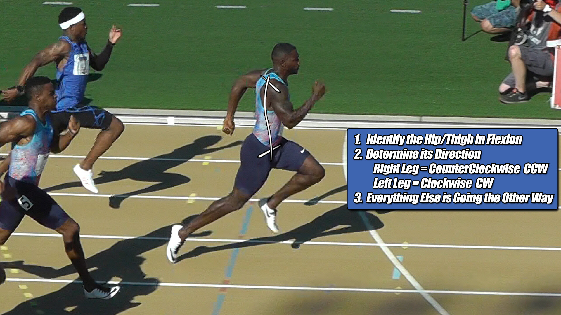
The first of two torque patterns everyone shares for not just sprinting, but all human locomotion… walking jogging, running is shown below:
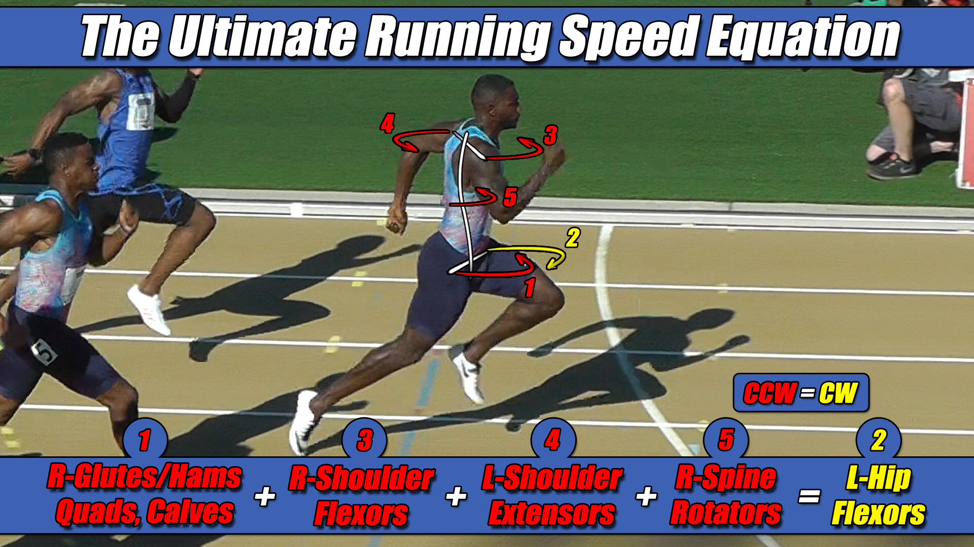 Left Hip Flexor Torque = CW. Everything Else CCW.
Decoding Torque Pattern 2 of 2
The athlete’s body has alternated to the other torque pattern. Repeat the process.
Apply the three steps to the runner in the figure below to determine the second of two torque patterns everyone shares for not just sprinting, but all human locomotion… walking. jogging, running:
- Identify the hip/thigh in flexion. This is what you need to key in on first, at the very beginning. In the image below, it’s the right hip.
- Determine the torque direction of this hip/thigh based on the following constants: Right Leg = CCW Left Leg = CW. Therefore, Since we identified it was the right hip, we know it’s CCW.
- Everything else is going the other way. In this case, that means the pushing leg, left arm, right arm, torso = CW.

The second of two torque patterns everyone shares for not just sprinting, but all human locomotion… walking jogging, running is shown below:
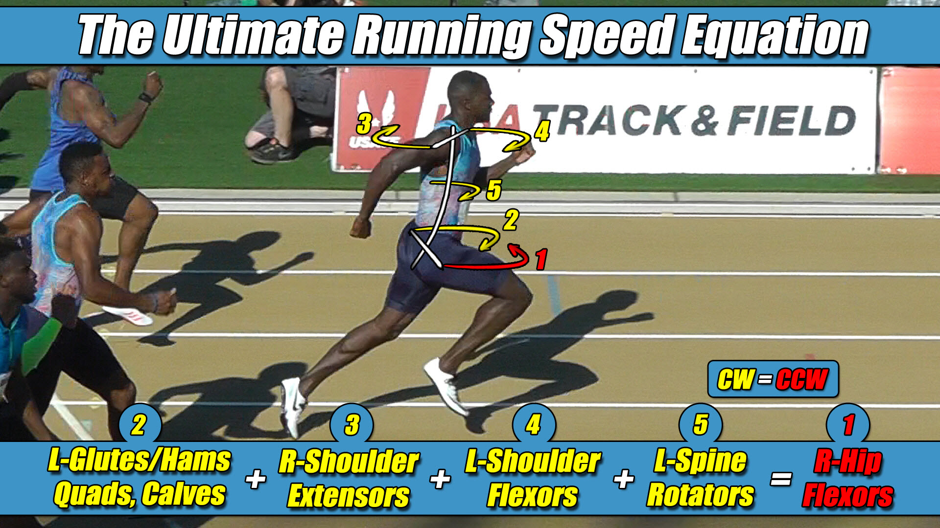
Right Hip Flexor Torque = CCW. Everything Else CW.
🏛️ Intellectual Property Notice & Legal Framework Boundaries
The Ultimate Running Speed Equation (URSE), along with its multi-axis pelvic torque constants and associated strength-balance profiling frameworks, represents the exclusive, proprietary intellectual property of Dr. Larry VanSuch. All rights reserved.
The clinical definitions outlined within this document function as established public prior art to protect the structural lineage of these discoveries.
Any unauthorized commercial exploitation, digital redistribution, or institutional replication of these geometric principles by outside entities without prior written consent is strictly prohibited.